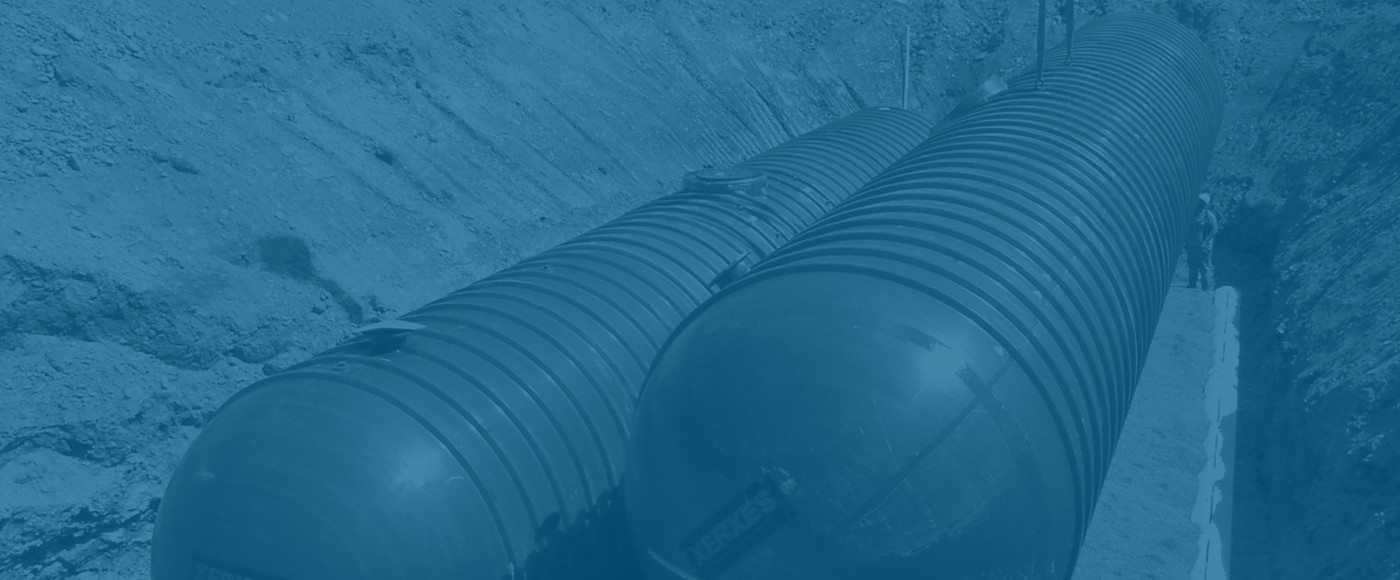
Fiberglass Underground Petroleum Storage Tanks & Piping 50+ Year History


Sullivan D. Curran P.E.,  Former Executive Director


50+ Year History: For more than 50 years, fiberglass underground petroleum storage tanks and piping have established an outstanding reputation for corrosion resistant, product compatible storage and distribution  of motor fuels, including today’s generation of biofuels, chemicals, and various petroleum products.


30 Year Limited Warranty: Institute tank and piping manufacturer’s warranty their petroleum tanks and piping for 30 years based on their confidence, which can only stem from a long history of success, and knowledge that properly installed UL Listed fiberglass tanks and piping will last for decades with little or no maintenance.


1960s: In the very early 1960s Owens Corning, a major glass fiber manufacturer, began manufacturing lightweight reinforced plastic underground storage tanks with ribs and hemispherical end caps designed to handle common burial site and loading conditions  Similarly, lightweight fiberglass pipe was developed that was designed for shipment to the job site in lengths up to 40 foot, easily installed with leak free joints, corrosion resistant, and able to withstand high pressures with a low friction flow rates. The tanks and piping were tested and listed by Underwriters Laboratories (UL)  Standards 1316, “Glass Reinforced Plastic Underground Storage Tanks for Petroleum Products, Alcohols, and Alcohol Gasoline Mixtures” and 971 “Standard for Nonmetallic Underground Piping for Flammable Liquids”, and Factory Mutual for the underground storage of flammable and combustible liquids.


1970s:  In the early 1970’s the major manufacturers of fiberglass tanks (Owens Corning, now Containment Solutions Inc. and Xerxes Corporation) and major manufacturers of fiberglass piping (Ameron and Smith Fiberglass, now NOV Fiber Glass Systems) trained major oil company personnel and their contractors to properly install fiberglass underground tanks and piping at vehicle refueling facilities and other industrial locations. Witnessing the early installation and performance success of fiberglass tanks and piping, state and local building officials recognized the  corrosion resistant advantages of properly installed underground storage tanks and piping. This, in turn, prompted model building and fire code organizations (e.g. National Fire Protection Association, Uniform Fire Code, Standard Fire Protection Code) to recognize and include fiberglass tanks, piping and their proper installation in their model codes.

1980’s and 1990’s: By 1980 certain major oil companies required UL listed tanks to be compatible with fuels with up to 100% ethanol and methanol. In 1983, the Underwriters Laboratories Listing UL 1316 was revised and a new listing was included for the storage of fuels with up to 100% ethanol and methanol. In 1988, the UL 971 Listing for fiberglass piping was also changed to include up to 100% ethanol and methanol.


2015:  On July 15, 2015 the Environmental Protection Agency’s (EPA’s) updated Underground Storage Tank Regulations (including piping) were published in the Federal Register. The updated regulations adds secondary containment release and detection requirements for new and replaced tanks and piping.

  • Double Wall: Today’s regulated (petroleum and chemical) fiberglass tanks and piping are both double walled with the ability to monitor the interstitial space for integrity, either hydraulically or with sensors.
  • Triple wall underground fiberglass tanks and piping systems are also available with two interstitial spaces for integrity monitoring and are typically used for large volume storage in ultra-sensitive environments.
  • Multi-compartment fiberglass tanks are being used more extensively today to store multiple products in the same tanks rather than storing different products separately in smaller tanks. Multi-compartment tanks reduce installation and other multiple storage tank operating costs.
  • Tank sizes: Underground fiberglass tank sizes range from 4 foot diameter with 600 gallons capacity to 12 foot diameter with 50,000 gallons capacity. Today, most fuel applications utilize 10 foot diameter single and multi-compartment tank capacities ranging from 25,000 to 50,000 gallons. Large tanks capacities are also typically used for water and wastewater treatment applications.
  • Piping sizes: Underground double wall fiberglass pressure piping and fittings are UL 971 listed materials for underground tank installations ranging from 2 through 6 inch diameters.
  • Limited Warranty: Fiberglass Tank & Pipe Institute manufacturers of the foregoing described UL listed fiberglass tanks, piping and fittings include a 30-year Limited Warranty.

sdc,  October 1, 2015

Microbial Influenced Corrosion (MIC) of Metals & Alloys in Fuel & Municipal Storage Tank and Piping Systems

Sullivan (Sully) D. Curran PE,  Former Executive Director

I. Introduction

The purpose of this paper is to describe:

  1. The conditions leading to accelerated MIC (Microbial Influenced Corrosion) which is sometimes referred to as hydrocarbon utilizing microbes “HUMbugs” in fuel and municipal storage tanks and piping systems. MIC contributes to the accelerated corrosion of metals and alloys that are exposed to corrosive environments such as soils, water and process chemicals. Certain microbe corrosive organic secretions (e.g., acetate) have been estimated to account for 20% of the total cost of such corrosion including reduced material strength and/or loss of containment.

  1. Laboratory, field testing and long term experience of corrosion protection provided by thermosetting plastic tanks and piping. This evidence will counter the misleading postulations that likely come from the fact that some polyesters are susceptible to biodegradation. Polyesters, both thermosetting and thermoplastic, can be purposely comprised of chemical segments that are biodegradable. These resins are designed to provide a material that can be composed in a landfill at the end of its useful life.

II. Background

  1. Accelerated Microbially Influenced Corrosion: MIC is corrosion accelerated by the action of microorganisms in the local environment. Facilities where MIC is prevalent include hydrocarbon and fuel (gas and liquid) storage (i.e., tanks), and transmission systems including municipal sewer and drinking water piping. Anaerobic or aerobic MIC microbes require water (i.e., condensed moisture, fresh, saline, distilled) and food sources necessary for their growth. The food sources range from single carbon molecules (e.g., carbon dioxide and methane) to certain complex polymers that are known to break down (i.e., deplasticize) in certain thermo plastics (e.g., seals, gaskets).

Microbes, bacteria and fungi are introduced into the storage tanks and piping systems along with dust particles and water condensed moisture through atmospheric venting systems. Microbes require both water and nutrients to multiply. It is recognized that negligible traces of water are sufficient to support microbial populations and food sources are plentiful. These nutrients include carbon, hydrogen, oxygen, nitrogen, sulfur, phosphorus and lesser elements such as calcium, sodium, iron, magnesium and copper in trace quantities. As a result, fuel and municipal tank storage and piping systems will provide the prerequisite water and nutrients to support microbial growth and proliferation.

  1. Biofilms: Microbial growth establishes communities, known as biofilms, which are a layer of microorganisms that proliferate at phase interfaces. They accumulate at the water/fuel interface as well as on tank walls and on equipment located above the liquid surface. The numbers of microbes within biofilms are orders of magnitude greater than microbes located elsewhere. For example, a 1-mm thick biofilm on a tank wall is 100 times the thickness of most fungi and 500 to 1,000 times the longest diameter of most bacteria. These biofilm communities are directly involved in MIC and result in accelerated metal corrosion.

B. Fuel Storage Tanks: Once inside the fuel tank the microbes may adhere to overhead surfaces and/or settle through the product. Some microbes will adhere to tank walls, some will collect at the fuel/water interface, and others will accumulate at the tank bottom.

a) Tank Bottom: Because microorganisms require both food and water for growth, the tank bottom interface is the most prevalent fuel/water interface. Thus, most growth and activity takes place at the tank bottom. Such microbes grow anaerobically and produce low molecular weight organic acids (formate, acetate, lactate and others). These acids accelerate the corrosion process by chemically etching the metal surface.

Galvanic corrosion: In addition, biofilm accumulations create electro potential gradients between surfaces that are covered with biofilms and surfaces that are not covered. This leads to different electrical potentials and the galvanic corrosion of the metal. Galvanic corrosion is known to cause a pattern of pinhole leaks in steel tanks and piping.

b) Tank Ullage: Tank refilling causes the ullage area to be replenished with hydrocarbon and water vapors, providing nutrients and moisture for microbial growth. Thus, there is a considerable area of fuel/water interface on the interior surface of the tank shell as well as on exposed in-tank equipment such as pumps and gauges. The biofilm that accumulates on tank walls is typically greater than 90% water. This water creates a substantial habitat for microorganisms.

c) Water Removal: Frequent water removal is important because microbes require water. However, reference ASTM D 6469 11.3.4 states, “Water removal is never 100% effective. Most tank configurations make it impossible to remove all water.” Water removal is never 100% effective for the following reasons:

  1. Most aboveground tank configurations employ flat and convex bottoms which will retain water after draining.

  1. While some underground tanks were installed on a level plane, tanks settle in time, tilt and retain some water at the bottom. Even properly titled tanks will retain water at the bottom as the suction pump causes the fuel to visibly vortex into the discharge stream and signals the operator to cease pumping before all of the water is removed.

  1. Daily diurnal breathing of vented (atmospheric) tanks introduces moisture and water condensation in the tanks, introducing new water that replenishes the tank ullage, moisture water at the tank’s bottom and water at the fuel/water interface.

C. Biocide Use and Cleaning per ASTM D 6469: There are three major groups of fuel biocides: fuel soluble, water soluble and universally soluble.

  1. Fuel soluble biocides are unstable or insoluble in water, where the microbes tend to grow.

  1. Water soluble biocides are insoluble in fuel; tend to be inexpensive and best used to shock-treat bottom-water contamination. However, water soluble biocides do not persist in fuel phase long enough to diffuse into system surface biofilms.

  1. Universally soluble biocides are stable in both fuel and water and have the advantage of affecting both biofilm and bottom-water microbes. The principle disadvantage is the high cost relative to the other biocide groups.

  1. Tanks & pipe cleaning: Heavily contaminated systems generally require tank and pipe cleaning in conjunction with biocide treatment and after cleaning the freshly charged fuel system should be retreated with a second biocide dose.

D. AWWA Journal (2014): DNA Microbial Analysis and Potable Water Distribution

This AWWA Journal paper discusses recent advances in DNA technology that will now allow nearly all microbes in a drinking water sample to be identified and quantified based on their DNA and be a likely substitute for the standard coliform tests which have been documented as failing to provide warning of public drinking water threats.

    1. Field studies: Studies have shown that many microbes are able to pass through treatment barriers and survive to colonize in drinking water distribution systems. Microbes that survive the treatment process can attach to pipe walls and begin forming robust biofilms.

  1. Pipe Corrosion: Initially pioneer bacteria attach and begin secreting extracellular polysaccharides (i.e., slime) that protects them from residual disinfectants and provides a more hospitable environment in which successor microbes can readily attach and begin to grow a more complex biofilm community. These biofilms may cause pipe corrosion.

c) Conclusion: Potable drinking water DNA field studies show that drinking water transmission piping and storage is subject to biofilms and MIC which will accelerate the corrosion of unprotected materials.

E. Fuel & Municipal Pipeline Corrosion Experience: NACE International’s January 2014 Materials Performance publication reported on comments from selected knowledgeable NACE international members and other experts on the impact of MIC as a “contributor to rapid corrosion of metals and alloys exposed to soils, seawater, distilled water, freshwater, crude oil, hydrocarbon fuels, process chemicals and sewage.” Following is a summary of their comments:

  1. MIC corrosion is underestimated: “Systems where MIC is especially important include hydrocarbon and fuel (gas and liquid) transmission and storage systems, as well as hazardous materials transport and storage structures. These systems provide adequate environmental conditions and substrates for microbial development and the participation of microorganisms in corrosion has been clearly demonstrated and MIC failures documented. Utilities such as drinking water and sewer systems also provide adequate conditions for MIC development; however, in such systems MIC has often been underestimated, as has corrosion in general.”

  1. MIC manifests as pitting corrosion: “MIC typically manifests itself as localized (i.e., pitting) corrosion – with a wide variation in rate, including rapid metal loss rates – both internally and externally on pipelines, vessels, tanks, and other fluid handling equipment.” “Often pitting is very isolated, with one hole surrounded by a number of shallower pits. Pitting rates range from a few mpy to more than 250 mpy.” “In almost all cases MIC produces localized attack that reduces strength and/or results in loss of containment.”

c) Where MIC is most like to occur: “…The places we expect MIC to occur experience rapid pitting, usually at interfaces where solids like scale, wax, and or other solids can settle out or precipitate.” In pipelines “areas downstream of welds, where cleaning pigs have difficulty removing deposits, as well as dead legs, low-velocity areas, and tank bottoms where solids and bacteria/biofilms can accumulate, are particularly susceptible to attack.”

d) MIC mitigation and its limitations: “Biocides are still the chemicals of choice when mitigating MIC; however, biocides usually need to be combined with a mechanical or chemical cleaning program to enhance their effectiveness, especially if the biofilms and corrosion are already firmly established.”

i. Deposits and biofilm removal: “…maintenance pigging (i.e., oil & gas pipelines) can be effective in removing deposits/biofilms that promote MIC” and “a further benefit of removing deposits is increasing the effectiveness of chemical treatment by allowing the chemical to reach the exposed metal surface.”

ii. Chemical treatment: “The main problem associated with the use of chemicals is the adaptation capacity of microorganisms that allow them to develop resistance mechanisms and, in some cases, the ability to biodegrade these products. Constant injection of the chemical products is necessary.”

e) MIC Corrosion Resistant Tanks & Piping: “The threat of MIC needs to be considered in the design of new projects to enable monitoring and mitigation for managing MIC during the operational stage of the asset. Materials selection should be based upon the anticipated operating conditions through the life of the asset and the intended design life.” (underline added)

III. Thermoset Fiberglass Tanks & Piping ~ Resistance to MIC

  1. Battelle Memorial Institute Aug, 2012 Report

Investigation of Corrosion in Systems Storing and Dispensing Ultra Low Sulfur Diesel (ULSD) in six (6) fiberglass underground storage tanks.

a) Battelle Conclusion: The “final hypothesis is that corrosion in systems storing and dispensing ULSD is likely due to the dispersal of acetic acid throughout USTs. It is likely produced by acetobacter bacteria feeding on low levels of ethanol contamination dispersed into the humid vapor space by the higher vapor pressure and, by disturbances during fuel deliveries, acetic acid are deposited throughout the system. This results in a cycle of wetting and drying of the equipment concentrating the acetic acid on the metallic equipment and corroding it quite severely and rapidly.” (underline added) [Fiberglass tank material was unaffected.]

B. US EPA ~ Corrosion in STP Sumps (3Q 2013) What Caused It and What can be Done About It? Headspace vapor testing from 64 tanks: Florida (35), Tennessee (16), Illinois (6), Wisconsin (4), California (2) and Iowa (1).

a) US EPA Conclusions: The three components that have resulted in tank sump MIC enhanced metal corrosion caused by acetobacter bacteria are:

i. ethanol to provide the food source,

ii. water (i.e., moisture) to live in, and

iii. bacteria secretions of acetic acid that corrodes metals. (underline added) [Fiberglas material was unaffected]

C. Assoc. of State and Territorial Solid Waste Management Officials (ASTSWMO) Compatibility of UST Systems with Biofuels (June 2013)

  1. ASTSWMO Conclusions:

  1. Biofuels are more soluble, have a higher water absorption capacity and are more conductive. Thus, higher solubility means seepage through non-metals (e.g., seals, thermoplastics) at the tank and sump interface.

  1. Higher water absorption means accelerated MIC metal corrosion.

  1. Higher conductivity accelerates corrosion in the presence of cathodic metals (e.g., steel), anodic metals (e.g., brass, aluminum, copper).

iv. “The Workgroup has not done any material testing to verify that these observations were the result of compatibility issues between the equipment and the fuel used, does not endorse any of the findings, and is not responsible for the accuracy, completeness, or usefulness of any information presented in the case summaries. [underlining added]

  1. NIST National Institute of Standards & Technology Corrosion Science (Jan.2014)

Corrosion of Copper and Steel Alloys in a Simulated Underground Storage-tank Sump Environment Containing Acid-producing Bacteria

  1. “Carbon steel corrosion rate was significantly higher when in a vapor-phase exposure as compared to immersed in a test solution. Carbon steel corrosion also consisted of pitting, which upon examination revealed pitting depths greater than those observed in the immersed condition.” (underlining added)

  2. “Copper corrosion when immersed in a test solution is on the order of that observed in the headspace. It is postulated that corrosion crystals form a more protective barrier to reduce corrosion.”

E. NACE Corrosion Expo. 2007 P.J Scott; CARIAD Consultants, Crete, Greece

Experiments on MIC of Steel and FRP Downhole Tubulars in West Kuwait Brines

  1. Laboratory tests showed that thermoplastics are resistant to attack by bacteria and fungi.”

  2. “FRP containing vinyl ester and epoxy resins were not attacked.”

  3. “FRP consisting of carbon fibers with epoxy resin has also been found to be susceptible to fungi.”

  4. “Although some experimental data indicate that FRP might be attacked by bacteria, there have been no reported field cases of biodeterioration of pipelines, flow lines or tubulars to date.” (underlining added)

F. Earlier Laboratory Studies: 1995 – 1998 MIC & Fiber Reinforced Composites

Microbial Growth on Fiber Reinforced Composite Materials; Ji-Dong et al

  1. 1995 Postulation that “…there may be degradation of the silane surface on glass fibers” ignores that microbes need a pathway to get to the glass, and the glass must de-bond from the resin in order for the 2 micron microbes to squeeze into a space between the fiber and resin of less than 1/2 of a micron.

  2. Ji-Dong’s 1997 later study concludes on page 368 “No significant difference of interlaminar shear strength was detected between the inoculated and the control composites.” In spite of the foregoing test result, the paper theorizes that “fungi were shown to be responsible for the degradation of composite material” However, the material adhesion occurring between the fiber surface and the resin matrix.” was in fact, unaffected in a standard industry test. (underlining added)

G. EPA Study Update (Sept. 2014 & 1Q 2015) Investigating Corrosion Observations of Metal Components in Underground Storage Tanks Storing Ultra-Low Sulfur Diesel

a) Tank vapor, bottom water and fuel collected from 42 UST sites (23 FRP & 19 steel) to analyze for corrosion factors and provided a preliminary hypothesis:

i. Both ethanol and glycerol pathways viable.

ii. Presence of corrosion does not appear to be influenced by tank material.

iii. Corrosion observed in each of the minimal, moderate & severe categories.

H. Microbial Insights, Inc. (2015 website)

a) Ethanol Utilizing Bacteria: Acetobacter catalyzes the oxidation of ethanol to acetic acid which can be a potential cause of corrosion.

b) Glycerol Utilizing Bacteria: Microbial degradation of glycerol, a byproduct of biodiesel production from fats, lead to the generation of lactic and propionic acid both of which have been observed at high concentrations in diesel fuels.

I. Manufacturer Field Experience – 1982 to January 2015

a) Resin manufacturers Listed by UL as certified suppliers for the manufacturer of corrosion resistant tanks and piping state there is an unblemished history of resin protection against accelerated MIC in more than 20 years of application experience.

b) Glass manufacturers do not have any evidence that glass fiber sizing may leach and/or hydrolyze to contribute to ethyl acetate found in certain tank bottom analysis.

c) Fiberglass pipe manufacturers have a history of successful sea water piping applications since 1982 and have not experienced accelerated MIC corrosion.

IV. Conclusions: Microbial Influenced Corrosion of Metals & Alloys in Fuel & Municipal Storage Tank and Piping Systems

  1. MIC accelerates the corrosion of metals, alloys and steel reinforced concrete by the action of microorganisms in hydrocarbon fuel, water storage tanks and transmission systems, including municipal sewer and drinking water piping.

  2. Microorganisms require both food and water for growth, with both readily available in hydrocarbon fuel, water storage tanks and transmission systems.

  3. MIC manifests itself as a galvanic pitting corrosion in mild steel metals.

  4. MIC mitigation is limited. Mitigation requires biofilm removal (cleaning) for chemical treatment to reach the exposed metal and alloy surfaces.

  5. Mandated higher ethanol blended gasolines and biodiesel blended diesel fuels are likely to experience accelerated metal and alloy corrosion in storage tank vapor and liquid spaces.

  6. Earlier 1995 through 1997 MIC laboratory corrosion studies of fiberglass reinforced thermosetting plastics focused on carbon fibers as a MIC fuel source and non-applicable glass fiber sizing theories.

  7. Fiberglass reinforced thermosetting plastic tanks and piping are not corroded by, nor provides a food source for accelerated microbial influenced corrosion (MIC).

References: See Institute paper: 1995-2015 Review: Laboratory and Field studies of the Cause for MIC Accelerated Corrosion in Petroleum and Municipal Storage Tanks and Piping.

Sdc 5/01/15

Attachment A

  1. ASTM D6469-99 “Standard Guide for Microbial Contamination in Fuels and Fuel Systems”

  2. Battelle Final Report (August 13, 2012) “Corrosion in Systems Storing and Dispensing Ultra Low Sulfur Diesel (ULSD), Hypotheses Investigation”

  3. EPA Office of Research and Development (2013) “Corrosion In STP Sumps”

  4. Oak Ridge National Laboratory: (May 2012) “Compatibility Study for Plastic, Elastomeric, and Metallic Fueling Infrastructure Materials Exposed to Aggressive Formulations of Ethanol-Blended Gasoline”

  5. Oak Ridge National Laboratory: (July 2012) “Analysis of Underground Storage Tank System Materials to Increased Leak Potential Associated with E15 Fuel”

  6. Oak Ridge National Laboratory: (August 2013) “Compatibility Study for Plastic, Elastomeric, and Metallic Fueling Infrastructure Materials Exposed to Aggressive Formulations of Isobutanol-Blended Gasoline’s”

  7. ASTSWMO (June 2013) “Compatibility of UST Systems with Biofuels”

  8. ASTSWMO (June 2014) “Development and Implementation of State Tanks Core Programs”

  9. NACE Materials Performance (January 2014) “A Closer Look at Microbiologically Influenced Corrosion”

  10. NIST (National Institute of Standards and Technology) (January 2014) Corrosion of copper and steel alloys in a simulated underground storage-tank sump environment containing acid-producing bacteria

  11. International Biodeterioration & Biodegradation (1995) Microbial Growth on Fiber Reinforced Composite Materials J-Dong Gru et al

  12. NACE Corrosion 96 Conference and Expo (1996) Fungal Degration of Fiber-Reinforced Composite Materials Ji-Dong Gru et al

  13. Journal of Industrial Microbiology & Biotechnology (1997) Fiber-reinforced polymeric composites are susceptible to microbial degradation Ji-Dong Gu

  14. NACE Corrosion 2007 Conference & Expo Experiments on MIC of Steel and FRP Downhole Tubulars in West Kuwait Brines P.J.B. Scott

  15. EPA Study Update (September 2014) Investigating Corrosion Observations of Metal Components in Underground Storage Tanks Storing Ultra-Low Sulfur Diesel

  16. U.S. Dept. of Energy Handbook for Handling,
    Storing, ad Dispensing E85 and Other Ethanol-Gasoline Blends
    (2013)

  17. Renewable Fuels Association (2009) E 85 Fuel Ethanol Industry Guidelines, Specifications and Procedures

  18. U. S. Dept. of Defense (2005) Microbiologically Influenced Corrosion a Bigger Problem than you think!

  19. Fiberglass Tank and pipe manufacturers:

  1. Owens Corning

  2. Containment Solutions Ltd.

  3. Xerxes Corporation

  4. NOV Fiber Glass Systems

  5. Hobas Pipe USA

  1. Fiberglass reinforced thermoset plastic resin and glass manufacturers:

a. AOC resins d.Syrgis Performance Initiators, Inc.

b. Ashland Performance Materials e. PPG Industries

c. Jushi Group f. Owens Corning

1995-2015 Review: Laboratory and Field Studies on the Cause of Accelerated MIC Corrosion in Petroleum and Municipal Storage Tank and Piping Systems

Sullivan (Sully) D. Curran PE, Former Executive Director

I. Executive Summary

The purpose of this paper is to provide information on the conditions that lead to microbial influenced corrosion (MIC) of metals and alloys and the corrosion protection provided by thermoset plastics, including the materials (i.e., glass, resins, additives) used in the manufacture of tanks and piping. MIC (sometimes referred to as hydrocarbon utilizing microbes, “HUMbugs”) contributes to the rapid corrosion of metals and alloys that are exposed to corrosive environments such as soils, water (i.e., fresh, saline, distilled), hydrocarbon fuels, sewage and process chemicals. Certain microbe corrosive organic secretions (e.g., acetate) have been estimated to account for 20% of the total cost of such corrosion including reduced material strength and/or loss of containment.

Anaerobic or aerobic MIC microbes require water (e.g., condensed moisture) and food sources necessary for their growth. The food sources range from single carbon molecules (e.g., carbon dioxide and methane) to certain complex polymers that are known to break down (i.e., deplasticize) in certain thermo (e.g., seals, gaskets) versus thermoset plastics.

II. Introduction

A. Microbially Influenced Corrosion: MIC is corrosion accelerated by the action of microorganisms in the local environment. Facilities where MIC is prevalent include hydrocarbon and fuel (gas and liquid) storage (i.e., tanks), transmission systems including municipal sewer and drinking water piping.

Microbes, bacteria and fungi are introduced into the storage tanks and piping systems along with dust particles and water condensed moisture through atmospheric tank venting systems. Microbes require both water and nutrients to multiply. It is recognized that negligible traces of water are sufficient to support microbial populations and food sources are plentiful. These nutrients include carbon, hydrogen, oxygen, nitrogen, sulfur, phosphorus and lesser elements such as calcium, sodium, iron, magnesium and copper in trace quantities. As a result, fuel and municipal tank storage and piping systems will provide the prerequisite water and nutrients to support microbial growth and proliferation.

Microbial growth establishes communities, known as biofilms, which are a layer of microorganisms that proliferate at phase interfaces. They accumulate at the water/fuel interface as well as on tank walls and on equipment located above the liquid surface. The numbers of microbes within biofilms are orders of magnitude greater than microbes located elsewhere. For example, a 1-mm thick biofilm on a tank wall is 100 times the thickness of most fungi and 500 to 1,000 times the longest diameter of most bacteria. These biofilm communities are directly involved in MIC and result in accelerated metal corrosion.

B. Fuel Storage Tanks: Once inside the fuel tank the microbes may adhere to overhead surfaces and/or settle through the product. Some microbes will adhere to tank walls, some will collect at the fuel/water interface and others will accumulate at the tank bottom.

a) Tank Bottoms: Because microorganisms require both food and water for growth, the tank bottom interface is the most prevalent fuel/water interface. Thus, most growth and activity take place at the tank bottom. Such microbes grow anaerobically and produce low molecular weight organic acids (formate, acetate, lactate and others). These acids accelerate the corrosion process by chemically etching the metal surface. In addition, biofilm accumulations create electro potential gradients between the surfaces that are covered with biofilms and those surfaces that are not covered. This leads to different electrical potentials and the galvanic corrosion of the metal. Galvanic corrosion is known to cause a pattern of pinhole leaks in steel tanks and piping.

b) Tank Ullage: Tank refilling causes the ullage area to be replenished with hydrocarbon and water vapors, providing nutrients and moisture for microbial growth. Thus, there is a considerable area of fuel/water interface on the interior surface of the tank shell as well as on exposed in-tank equipment such as pumps and gauges. The biofilm that accumulates on tank walls is typically greater than 90% water. This water creates a substantial habitat for microorganisms.

c) MIC Prevention: Frequent water removal is important because microbes require water. However, reference ASTM D 6469 11.3.4 “Water removal is never 100% effective. Most tank configurations make it impossible to remove all water.” Water removal is never 100% effective for the following reasons:

  1. Most aboveground tank configurations employ flat and convex bottoms which will retain water after draining.

  1. While some underground tanks were installed on a level plane, tanks settle in time, tilt and retain some water at the bottom. Even properly titled tanks will retain water at the bottom as the suction pump causes the fuel to visibly vortex into the discharge stream and signals the operator to cease pumping before all of the water is removed.

  1. Daily diurnal breathing of vented (atmospheric) tanks introduces moisture and water condensation in the tanks, introducing new water that replenishes the tank ullage, moisture water at the tank’s bottom and water at the fuel/water interface.

C. Fuel & Municipal Pipeline Corrosion Experience: NACE International’s January 2014 Materials Performance publication reported on comments from selected knowledgeable NACE international members and other experts on the impact of MIC as a “contributor to rapid corrosion of metals and alloys exposed to soils, seawater, distilled water, freshwater, crude oil, hydrocarbon fuels, process chemicals and sewage.” Following is a summary of their comments:

  1. MIC corrosion is underestimated: “Systems where MIC is especially important include hydrocarbon and fuel (gas and liquid) transmission and storage systems, as well as hazardous materials transport and storage structures. These systems provide adequate environmental conditions and substrates for microbial development and the participation of microorganisms in corrosion has been clearly demonstrated and MIC failures documented. Utilities such as drinking water and sewer systems also provide adequate conditions for MIC development; however, in such systems MIC has often been underestimated, as has corrosion in general.”

  1. MIC manifests as pitting corrosion: “MIC typically manifests itself as localized (i.e., pitting) corrosion – with a wide variation in rate, including rapid metal loss rates – both internally and externally on pipelines, vessels, tanks, and other fluid handling equipment.” “Often pitting is very isolated, with one hole surrounded by a number of shallower pits. Pitting rates range from a few mpy to more than 250 mpy.” “In almost all cases MIC produces localized attack that reduces strength and/or results in loss of containment.”

c) Where MIC is most like to occur: “…the places we expect MIC to occur experience rapid pitting, usually at interfaces where solids like scale, wax, and/or other solids can settle out or precipitate.” In pipelines “areas downstream of welds, where cleaning pigs have difficulty removing deposits, as well as dead legs, low-velocity areas, and tank bottoms where solids and bacteria/biofilms can accumulate, are particularly susceptible to attack.”

d) MIC mitigation and its limitations: “Biocides are still the chemicals of choice when mitigating MIC; however, biocides usually need to be combined with a mechanical or chemical cleaning program to enhance their effectiveness, especially if the biofilms and corrosion are already firmly established.” (see below section D on Biocide Use)

i. Deposits and biofilm removal: “…maintenance pigging (i.e., oil & gas pipelines) can be effective in removing deposits/biofilms that promote MIC” and …” a further benefit of removing deposits is increasing the effectiveness of chemical treatment by allowing the chemical to reach the exposed metal surface.”

ii. Chemical treatment: “The main problem associated with the use of chemicals is the adaptation capacity of microorganisms that allow them to develop resistance mechanisms and, in some cases, the ability to biodegrade these products. Constant injection of the chemical products is necessary.”

e) MIC Corrosion Resistant Tanks & Piping: “The threat of MIC needs to be considered in the design of new projects to enable monitoring and mitigation for managing MIC during the operational stage of the asset. Materials selection should be based upon the anticipated operating conditions through the life of the asset and the intended design life.” (underline added)

D. Biocide Use and Cleaning per ASTM D 6469: There are three major groups of fuel biocides: fuel soluble, water soluble and universally soluble.

  1. Fuel soluble biocides are unstable or insoluble in water, where the microbes tend to grow.

  1. Water soluble biocides are insoluble in fuel, tend to be inexpensive and are best used to shock-treat bottom-water contamination. However, water soluble biocides do not persist in fuel phase long enough to diffuse into system surface biofilms.

  1. Universally soluble biocides are stable in both fuel and water and have the advantage of affecting both biofilm and bottom-water microbes. The principle disadvantage is the high cost relative to the other biocide groups.

d) Tanks & pipe cleaning: Heavily contaminated systems generally require tank and pipe cleaning in conjunction with biocide treatment and, after cleaning, the freshly charged fuel system should be retreated with a second biocide dose.

III. Battelle Memorial Institute Aug, 2012 Investigation of Corrosion in Systems Storing and Dispensing Ultra Low Sulfur Diesel (ULSD)

A. Objective: Conduct a research project to establish the factors leading to the accelerated corrosion of in-tank metal equipment (e.g., steel, copper) and deterioration of polymers (seals, gaskets) in ULSD storage and dispensing systems. Such in-tank metal equipment corrosion was identified in six non-corroded fiberglass underground storage tanks (USTs). The fiberglass tanks were free from deterioration, ranged in age of 13 to 24 years, and were located as follows: North Carolina (1), New York (2) and California (3). The hypothesis focused on MIC as the cause of accelerated in-tank equipment corrosion and the analysis of chemical constituents in the fuel, water and headspace vapor within the USTs. Also included was the question, if product additives (i.e. ethanol, biodiesel) were directly or indirectly a source for the microbe nutrients that result in the corrosive metabolites.

B. Results: Acetate was measured in all six bottom water samples and ethanol was identified in five of the six water bottoms. Four different tank DNA samples were of high quality and identified the presence of acetic acid produced by acetobacter bacteria, which requires oxygen and can use ethanol as an energy source. Thus, MIC is likely accelerating the other corrosive tank bottom water characteristics that included high conductivity, acidic pH and three tanks with high chloride concentrations.

C. Investigation Postulations and Responses: The Battelle study Table 10 “Summary of Water Bottom Sample Results” presented chemical analysis results on the water bottom samples. Glycolate was detected at four of the six sites and GC-MS scans indicated the presence of alcohols, acids and amines. It was postulated that these chemicals and methyl vinyl ketone (MEK) could have leached from the tank shells.

Following is a summary of the postulations and fiberglass tank material supplier responses to Battelle and work group questions:

  1. Glycolate and Acetic Acid: “Glycolate, a related compound to acetic acid, was detected in appreciable amounts at four of six tank water bottoms.”

Note: (1) Glycolate was less than 100 ppm in two of the four tanks.

(2) One of the tanks was a single wall tank that did not have an interstitial space [i.e. no liquid leak indicator.]

  1. #1 Question: Is glycol used as a leak indicator in double wall tanks? And, if propylene glycol is used as a leak indicator in the double wall tank sump, could it leak into the tank bottom?

Answers:

  1. Brine, not glycol, is used as the leak indicator in fiberglass double wall tanks.

  1. While propylene glycol may be used in some double wall tank sumps, there is no communication between the sump and the tank interstitial spaces.

  1. Glycolate/glycolic acid is not a decomposition product from propylene glycol.

c) #2 Question: Can polyester or vinyl ester resins hydrolyze to release glycol and acid if allowed to stay in contact with water?

Answers:

  1. No quantified species in Table 10 can be derived from typical USTs unsaturated polyester or vinylester resin decomposition including acetic acid.

  2. No leaching of acetic acid has been experienced in the history of fiberglass potable water storage tanks and fiberglass potable water transporting pipelines.

  1. #3 Question: Two tanks may indicate components from resins. Table 10 shows MEK at one site and phthalate at another. Is it possible for MEKP and MEKPO to be responsible for the acetic and formic acids?

Answers:

  1. The methyl ethyl ketone peroxide (MEKP) contains a simple phthalate, dimethyl phthylate. This phthalate is used as part of the safety diluents or phlegmatizers to increase the stability and product quality of MEKP. The dimethyl phthalate becomes immobilized within the thermoset resin. Resin testing includes boiling the thermoset resin sample in water. The amount of dimethyl phthalate extracted into the boiling water is not significant, typically below 100 ppm.

  1. MEKP and MVK are very reactive materials that would polymerize and become immobilized within the thermoset resin during cure of the resin and/or post cure of the tank. Thus acetic and formic acids could not be coming from the thermoset resin tank.

  1. #4 Question: Is glass fiber sizing a potential source of ethyl acetate and acetic acid? And, is Fluorine used in formulating the E-glass as a binder or adhesive (i.e., sizing)?

Answers:

  1. Ethyl acetate has not been used in any of the sizing systems in thousands of size formulations that manufacturers are aware of.

  1. Acetic acid is used to adjust the pH of a silane coupling agent premix which is an important sizing ingredient. However, it and other VOCs (volatile organic compounds) are readily evaporated during the drying of glass fiber, forming cakes. The drying temperatures are generally in the 125 to 130 degrees C range, well above the boiling point of acetic acid (118-119 degrees C), methanol (65 degrees C) or ethanol (78.4 degrees C).

  1. Fluorine was used more than 15 years ago, but to reduce air emissions of boron and fluorine as acid rain pollutants, it was reduced to 0.5-1.0%. Glass content in the tank corrosion liner is typically 25-35%, which makes the sizing amount less than 0.5% of the FRP laminate, hardly a plausible source of acetic acid.

D. Summary of fiberglass tank material suppliers to questions regarding potential tank wall material leaching of glycolate and acetic acid: Degradation of the unsaturated polyester resin leading to gycolate and/or acetate would be associated with significant tank degradation visible to the eye and measured by loss of structural properties. This was not the case with the six older fiberglass storage tanks (i.e. 13, 14, 21, 21, 22, & 24 years old) in the Battelle study.

E. Battelle Conclusion: The “final hypothesis is that corrosion in systems storing and dispensing ULSD is likely due to the dispersal of acetic acid throughout USTs. It is likely produced by acetobacter bacteria feeding on low levels of ethanol contamination dispersed into the humid vapor space by the higher vapor pressure and by disturbances during fuel deliveries when acetic acid is deposited throughout the system. This results in a cycle of wetting and drying of the equipment concentrating the acetic acid on the metallic equipment and corroding it quite severely and rapidly.”

IV. US EPA ~ Corrosion in STP Sumps (3Q 2013)

What Caused It and What can be Done About It?

A. Objective: Confirm the hypothesis that acetic acid produced by acetobacteria biodegradation of ethanol was occurring in UST submerged turbine sumps and causing the accelerated corrosion of iron and copper equipment components. The research staff of the U.S. Environmental Protection Agency provided sampling kits to state regulators to measure concentrations of ethanol and acetic acid in the vapor space of underground storage tank STP sumps. The sample kits were returned to EPA’s Ada, Oklahoma laboratory for analysis. Samples were acquired from Florida (35), Tennessee (16), Illinois (6), Wisconsin (4), California (2) and Iowa (1) for a total of 64.

B. Results: While standing water was in 7 sumps that exhibited corrosion, 61 of the sumps had high concentrations of ethanol or acetic acid in the vapor space samples (≥1,000 mg/L), with the remaining at lower concentrations. There was no appreciable difference between tanks that contained premium, regular E10 blended gasolines or E85 fuels.

Thirty nine photographs were available and showed iron or copper corrosion, typically in sumps where the air space in the sump included ethanol or acetic acid.

C. Conclusions: The three components that have resulted in tank sump MIC enhanced metal corrosion caused by acetobacter bacteria are (a) ethanol to provide the food source, (b) water (i.e., moisture) to live in and (c) bacteria secretions of acetic acid that corrode metals.

D. MIC Mitigation and its Limitations: Ideally the goal is to remove one of the following three components that encourage MIC growth:

a) Stop ethanol vapors from migrating into the tank sump from the tank ullage via STP, ATG and other riser pipes/fittings installed in the sump.

b) Stop the accumulation of standing water in the sump. However, sump standing water was in only 7 of the 61 sumps. It would be difficult to control the high concentrations of condensed water and resulting corrosion on the pump head and other sump equipment.

c) Retard the growth of microbes by adding biocides. This may be effective if standing water is present and biocides were added to standing water. However, without standing water, the addition of biocides may not reduce bacteria in the vapor space.

E. Comment: Designing and maintaining: (i) tight vapor free tank to sump accessory and pipe interfaces to prevent ethanol vapors from the tank ullage. This is likely a better alternative than maintaining a (ii) wet and humidity free sump or (iii) biocides to control microbial growth.

V. Assoc. of State and Territorial Solid Waste Management Officials (ASTSWMO) Compatibility of UST Systems with Biofuels

June 2013

This ASTSWMO document was prepared as a resource for State UST Program staff, UST owners/operators, contractors and consultants for evaluating equipment compatibility when storing biofuels, pursuant to EPA’s compatibility requirement (40 CFR Part 280.32). Owners and operators of USTs, regulated under 40 CFR part 280, are required to demonstrate compliance with EPA compatibility requirements when storing regulated substances, including biofuel blends containing greater than 10% ethanol or diesel containing greater than 20% biodiesel.

A. The document states that:

  1. Biofuels are more soluble, have a higher water absorption capacity and are more conductive. Thus, higher solubility means seepage through non-metals (e.g., seals, thermoplastics) at the tank and sump interface.

  1. Higher water absorption means accelerated MIC metal corrosion.

  1. Higher conductivity accelerates corrosion in the presence of cathodic metals (e.g., steel), and anodic metals (e.g., brass, aluminum, copper).

B. Case Summaries: Fiberglass Tank Material Compatibility Observations

* 1: Phoenix, AZ: 24-yr old 10,000 gal double wall FRP tank; E-10 fuel.

Purported bottom cracks; tank lined and put back into service

2. Tucson AZ: 26-year old 10,000 gal single wall FRP tank; E-10 fuel

Purported end cap crack; tank removed

*3. Yuma, AZ: 28 year old 10,000 gal single wall tank: E-10 fuel.

Unknown source of purported leak; tank repaired and put back into service

*4. Yuma, AZ: 28 year old single wall FRP tank

Unknown source of purported leak; tank repaired and put back into service

14. Hobbs, New Mexico: 25-yr old 8,000 gal FRP tank; Non-leaker

Purported tank broke when removed

*18. Haleiwa, HI: 26-year old FRP tank; E-10

Non-leaking tank was cleaned prior to storing blended fuels,

Purported bottom crack; tank lined and put back into service

*19. Kailua, HI: 25-yr old FRP tank; E-10 fuel

Non-leaking tank interior cleaned prior to storing blended fuel

Purported new tank liner did not adhere to tank walls, tank relined

Tank put back in service

*20. Waipahu, HI: 23-yr old double wall FRP tank; E-10 fuel

Non-leaking tank interior cleaned prior to storing blended fuels

Purported new tank liner installed; tank put back into service

Second liner failed; tank removed from service

21. Honolulu, HI: 26-yr old FRP single wall tank; E-10 fuel

Non- leaking tank interior cleaned prior to storing blended fuel

Purported failure of bottom gel coat; tank removed from service

22. Kihei, HI: 27 yr-old FRP single wall FP tank; E-10 fuel

Non-leaking tank interior cleaned prior to storing blended fuel

Purported failure of bottom gel coat; tank removed from service

C. Case Summary Comments:

  1. Seven of the ten tanks (Note*) were structurally sound, lined and put back into service.

Comment: If MIC damage was prevalent, the tank interiors would not likely qualify for relining.

b) All case study tanks are over 20 years old (i.e., 24 to 28 years).

Prior to 1990, Institute member manufactured tanks were designed for E-10, the maximum legal gasohol blend. However, there is evidence that ethanol blended E-10 was known to exceed the 10% ethanol blend ratio. Higher than 10% ethanol fuel blends were recognized in the following Oak Ridge reports:

  1. May 2012 Oak Ridge report: (page xvi) “… water, trace levels of sodium chloride, acid and sulfuric acids “…are found in ethanol-gasoline fuels and represent potential high contamination conditions for fuel-grade ethanol.”

  1. August 2013 Oak Ridge report (page 1, mid-paragraph 2) “….surveys indicated that the actual concentration of ethanol in E-10 dispensers has been noted to vary by as much as 2%.” (underlining added)

Comment: Case studies of older than pre-1990 tanks where the ethanol blends were higher than the legal 10%, and/or other corrosion factors cited by Oak Ridge were present and detract from the Case study’s usefulness to identify MIC tank damage.

[Note: By 1990 Institute member manufactured FRP tanks were designed for up to 100% ethanol.]

c) Five of the ten tanks were located in Hawaii. In all five of the Hawaii cases an unknown interior tank cleaning method was used. The tanks were non-leakers prior to tank cleaning and then leaked after cleaning.

Comment: The tanks were likely damaged by tank cleaning, rather than MIC.

D. Unsubstantiated and Unendorsed Opinions on Fiberglass Tank Compatibility:

  1. Page C-1: “The Workgroup has not done any material testing to verify that these observations were the result of compatibility issues between the equipment and the fuel used, does not endorse any of the findings, and is not responsible for the accuracy, completeness, or usefulness of any information presented in the case summaries.” [underline added]

  1. Page 6: “The views and opinions of case summary submitters do not necessarily state or reflect those of the ASTSWMO Alternate Fuels Workgroup.” [underline added] However, it is purported that “….field observations also suggest there may be some impacts to fiberglass USTs.” And it is purported that “In some regions of the country, mounting evidence from failure and field observations also suggests there may be some impacts to fiberglass USTs.”

  1. Page 7: It is purported that “Hydrocarbon Utilizing Microbes HUMbugs also can dissolve the resin holding the fibers together in a fiberglass tank, and use it for food, thus weakening the tank.”

E. Comments on ASTSWMO Case Summaries and Opinion:

  1. Case Studies: Superficial examination was in a narrow geographic range (i.e., AZ & HI) of tank bottom leaks, most of which were repaired and tanks put back into service. There was no supporting evidence of corrosive microbe biofilms or MIC.

  1. While the Workgroup members did not agree “on any of the findings”, the report makes the unsubstantiated statement that microbes can use FRP resin as a food source.

VI. DNA Microbial Analysis and Potable Water Distribution

AWWA Journal ~ March, 2014

This AWWA Journal paper discusses recent advances in DNA technology that will now allow nearly all microbes in a drinking water sample to be identified and quantified based on their DNA and be a likely substitute for the standard coliform tests which have been documented as failing to provide warning of public drinking water threats. Further, the cost of DNA testing is reduced and is being used in drinking water field studies.

A. Field Studies have shown that many microbes are able to pass through treatment barriers and survive to colonize in drinking water distribution systems. Microbes that survive the treatment process can attach to pipe walls and begin forming robust biofilms.

B. Pipe Corrosion: Initially pioneer bacteria attach and begin secreting extracellular polysaccharides (i.e., slime) that protects them from residual disinfectants and provides a more hospitable environment in which successor microbes can readily attach and begin to grow a more complex biofilm community. These biofilms may cause pipe corrosion.

C. Conclusion: Potable drinking water DNA field studies show that drinking water transmission piping is subject to biofilms and MIC which will accelerate the corrosion of unprotected materials.

VII. Corrosion of Copper and Steel Alloys in a Simulated Underground Storage-tank Sump Environment Containing Acid-producing Bacteria

NIST National Institute of Standards and Technology

Corrosion Science – January 2014

A. Problem: The consumption of alternative mandated fuels has increased significantly in the U.S. including ethanol and biodiesel and is projected to increase significantly. However, the current infrastructure was designed for unblended fuel and may not be compatible with these alternative fuels. Earlier studies revealed that there was rapid corrosion of steel metals and copper alloys in both the vapor (head space) and aqueous solution (tank bottom).

B. Objective: This NIST laboratory study used new equipment and test methods to study the corrosion of metal (steel and copper) tank sump components either immersed in ethanol-water solutions inoculated with bacteria, or exposed to vapors above the medium over a 30 day period. The new test methods included:

  1. Head Space testing chamber: Used to evaluate metal components exposed to ethanol and acetic-acid vapor components in a pure atmosphere.

  1. Immersion and head space testing with Acetobacter acetic to generate acetic-acid vapor with biological properties (e.g., bacterial attachment) versus acetic acid solution alone. Previous corrosion experiments used acetic acid from abiotic sources rather than a biotic source which may not replicate corrosion induced by microbes.

C. Conclusions: Copper corrosion when immersed in a test solution is on the order of that observed in the headspace. It is postulated that corrosion crystals form a more protective barrier to reduce corrosion.

Carbon steel corrosion rate was significantly higher when in a vapor-phase exposure as compared to immersed in a test solution. Carbon steel corrosion also consisted of pitting, which upon examination revealed pitting depths greater than those observed in the immersed condition. The NIST study confirmed metal corrosion damage in UST sumps similar to that seen by field inspectors.

VIII. 2007 NACE Corrosion Expo.

Experiments on MIC of Steel and FRP Downhole Tubulars in West Kuwait Brines P.J Scott; CARIAD Consultants, Crete, Greece

A. Problem: Oil field secondary recovery is common in oilfields; however, the injection water will sour, cause plugging and corrosion in fields that had been previously trouble free. Brine water is known to contain dissolved inorganic salt which is higher than that found in sea water. Oil field secondary recovery involves injecting brine and sour water with the potential of MIC plugging and corrosion in oil fields previously uncontaminated.

B. Objectives: This laboratory study was to determine: (1) the growth of marine bacteria in brines, (2) the corrosion resistance of brine water in candidate steel alloys and FRP tubular materials and (3) the biodeterioration of fiber reinforced plastic.

FRP tubular samples including phenolic, vinyl ester and epoxy resins were exposed to acid producing bacteria. SEM examination showed that the vinyl ester and epoxy resins were not damaged; however, testing of the phenolic samples was inconclusive when the phenolic samples could not be properly prepared for SEM without damage.

C. Conclusions:

  1. Laboratory tests showed that thermoplastics are resistant to attack by bacteria and fungi.”

  2. “Predamaged areas of the gel coat of experimental coupons did not appear to be sensitive to attack by the bacteria.”

  3. “FRP consisting of carbon fibers and epoxy resin has also been found to be susceptible to fungi.”

  4. “FRP containing vinyl ester and epoxy resins was not attacked.”

  5. “Although some experimental data indicate that FRP might be attacked by bacteria, there have been no reported field cases of biodeterioration of pipelines, flow lines or tubulars to date.”

IV. Earlier Laboratory Studies: 1995, 1996, 1997

Harvard University; Ji-Dong et al

A. Microbial Growth on Fiber Reinforced Composite Materials

a) 1995 International Biodeterioration & Biodegradation paper

Laboratory study to determine if microorganisms pose a threat to the structural integrity of composite materials. The following five composite samples were exposed to a fungal consortium for 5 weeks and examined by a scanning electronic microscopy (SEM):

Resins: fluorinated polyimide Glass Fiber (P-25 Fisher Scientific, Pittsburg, PA)

bimaleimide carbon (P-100) Amoco Performance Prod.)

poly (ether-ether-ketone) carbon

epoxy carbon

epoxy carbon

Note: four of five samples used carbon fibers; but study postulated on glass fiber sizing.

The basis for the 1995 study is an earlier 1994 Wagner et al study that postulated there may be degradation of the silane surface on glass fibers and this disbonding may “result in fiber disbonding and delamination when a composite is under stress.” [page 201] Thus, the paper hypothesized that “It is probable that the fungi were using the sizing materials as a carbon and energy source.” (underline added) [page 203]

b) 1996 NACE Corrosion 96 Conference and Exposition

This 1996 laboratory study included the application of electrochemical impedance spectroscopy (EIS) to determine if glass and carbon fibers are susceptible to the growth of microorganisms. While the former carbon/glass fiber samples were used in this study, the difference is purported to be that “the former utilized a fungal consortium enriched from degraded polymetic materials while the latter used a constituted bacterial consortium of bacterial species having diverse physiological functions.”

The paper hypothesized that “chemicals from the composites may serve as a carbon and energy source for the growth of fungi.”

c) 1997 Journal of Industrial Microbiology & Biotechnology

This 1997 laboratory study included 179 days of monitoring EIS spectra purported to show that there was “a continuous deterioration of the matrix after inoculation. However, the composite held under aseptic conditions showed minimal changes of the impedance and phase angle.” And “No significant difference of interlaminar shear strength was detected between the inoculated and the control composites.” The inability of the mechanical test to detect any differences between the inoculated and control composites is due to the insensitivity of the technique to a small proportion of disbonding over the whole composite matrix.

d) Comments on 1995, 1996 & 1997 Ji-Dong et al studies:

    1. If sizing chemicals were attacked by microbes, the microbes would:

  1. need a pathway to get to the glass, and

  2. the glass must de-bond from the resin in order for the 2 micron microbes,

  3. to squeeze into a space between the fiber and resin of less than 1/2 of a micron.

    1. See sizing discussion in section III. Battelle Memorial Institute Aug, 2012 Investigation of Corrosion in Systems Storing and Dispensing Ultra Low Sulfur Diesel (ULSD)

    2. Four of the five study fibers are carbon versus glass fibers. Further, the resins and glass fibers are not used by Institute manufacturers of UL Listed 1316 fiberglass tanks UL 971 piping or Hobas pipe.

    3. The foregoing Section VIII Experiments on MIC of Steel and FRP Downhole Tubulars in West Kuwait Brines study concluded: “FRP consisting of carbon fibers and epoxy resin has also been found to be susceptible to fungi.” (underline added) Thus, fiberglass tanks and piping manufactured with glass fibers have not been shown as susceptible to fungi.

    4. Ji-Dong’s 1997 study concludes on page 368 “No significant difference of interlaminar shear strength was detected between the inoculated and the control composites.” “The inability of the mechanical test to detect any differences between inoculated and control may be due to the sensitivity of the technique to a small proportion of disbonding over the whole composite matrix.”

In spite of the foregoing test result, the paper claims that “fungi were shown to be responsible for the degradation of composite material” when the material adhesion occurring between the fiber surface and the resin matrix was in fact unaffected.

e) Summary: The three Ji-Dong studies do not recognize that fiberglass thermoplastics are engineered products for their intended applications. For example, there are resins designed to be biodegradable and provide a material that may be composted in a landfill.

V. September 2014 – 1Q 15 EPA Study Updates

Investigating Corrosion Observations of Metal Components in Underground Storage Tanks Storing Ultra-Low Sulfur Diesel

A. Problem: Increase of ethanol in blended gasolines and biodiesel in Ultra-Low Sulfur Diesel are likely increasing microbiologically influenced corrosion (MIC). Inconclusive, but likely, that ethanol, a food source for acetobacteria, is excreting acetic acid and biodiesel containing glycerol is forming propionic acid. The acids may be the cause of accelerated corrosion in steel and copper metals in the tank liquid bottom and tank & sump vapor spaces.

B. Objectives: 1. Build on 2012 Battelle and EPA hypotheses and possibly come up with new pathways to identify the source of high level MIC corrosion.

2. Use tank vapor, bottom water and fuel collected from 42 UST sites (23 FRP & 19 steel) to analyze for corrosion factors.

C. Preliminary Hypotheses:

1. Both ethanol and glycerol pathways are viable.

2. Presence of corrosion does not appear to be influenced by tank material.

3. Corrosion observed in each of the minimal, moderate, and severe categories in both steel and fiberglass tanks.

VI. Microbial Insights, Inc.

Website Quantification of bacterial types implicated in MIC

MIC Bacteria Quantification:

  1. Ethanol Utilizing Bacteria: Acetobacter catalyzes the oxidation of ethanol to acetic acid which can be a potential cause of corrosion.

  2. Glycerol Utilizing Bacteria: Microbial degradiation of glycerol, a byproduct of biodiesel production from fats, lead to the generation of lactic and propionic acid both of which have been observed at high concentrations in diesel tanks.

VII. Conclusions: Microbial Influenced Corrosion

  1. MIC accelerates the corrosion of metals, alloys and steel reinforced concrete by the action of microorganisms in hydrocarbon fuel & water storage tanks and transmission systems, including municipal sewer and drinking water piping.

  1. Microorganisms require both food and water for growth, with both readily available in hydrocarbon fuel, water storage tanks and transmission systems.

  1. MIC manifests itself as a pitting corrosion in mild steel metals.

  1. MIC mitigation is limited. Mitigation requires biofilm removal (cleaning) and for chemical treatment to reach the exposed metal and alloy surfaces.

  1. Mandated higher ethanol blends in gasoline and biodiesel blended diesel fuels are likely to experience accelerated metal and alloy corrosion in storage tank vapor and liquid spaces.

  1. Earlier 1995 through 1997 MIC corrosion studies of fiberglass reinforced thermosetting plastics focused on carbon fibers as a MIC fuel source and non-applicable glass fiber sizing theories.

  1. Fiberglass reinforced thermosetting plastic tanks and piping are not corroded by, nor provide a food source for, microbial influenced corrosion (MIC).

VII. References

  1. ASTM D6469-99 “Standard Guide for Microbial Contamination in Fuels and Fuel Systems”

  2. Battelle Final Report (August 13, 2012) “Corrosion in Systems Storing and Dispensing Ultra Low Sulfur Diesel (ULSD), Hypotheses Investigation”

  3. EPA Office of Research and Development (2013) “Corrosion In STP Sumps”

  4. Oak Ridge National Laboratory: (May 2012) “Compatibility Study for Plastic, Elastomeric, and Metallic Fueling Infrastructure Materials Exposed to Aggressive Formulations of Ethanol-Blended Gasoline”

  5. Oak Ridge National Laboratory: (July 2012) “Analysis of Underground Storage Tank System Materials to Increased Leak Potential Associated with E15 Fuel”

  6. Oak Ridge National Laboratory: (August 2013) “Compatibility Study for Plastic, Elastomeric, and Metallic Fuelling Infrastructure Materials Exposed to Aggressive Formulations of Isobutanol-Blended Gasoline’s”

  7. ASTSWMO (June 2013) “Compatibility of UST Systems with Biofuels”

  8. ASTSWMO (June 2014) “Development and Implementation of State Tanks Core Programs”

  9. NACE Materials Performance (January 2014) “A Closer Look at Microbiologically Influenced Corrosion”

  10. NIST (National Institute of Standards and Technology) (January 2014) Corrosion of copper and steel alloys in a simulated underground storage-tank sump environment containing acid-producing bacteria

  11. International Biodeterioration & Biodegradation (1995) Microbial Growth on Fiber Reinforced Composite Materials J-Dong Gru et al

  12. NACE Corrosion 96 Conference and Expo (1996) Fungal Degration of Fiber-Reinforced Composite Materials Ji-Dong Gru et al

  13. Journal of Industrial Microbiology & Biotechnology (1997) Fiber-reinforced polymeric composites are susceptible to microbial degradation Ji-Dong Gu

  14. NACE Corrosion 2007 Conference & Expo Experiments on MIC of Steel and FRP Downhole Tubulars in West Kuwait Brines P.J.B. Scott

  15. EPA Study Updates (September 2014, 1Q 2015) Investigating Corrosion Observations of Metal Components in Underground Storage Tanks Storing Ultra-Low Sulfur Diesel

  16. U.S. Dept. of Energy Handbook for Handling,
    Storing, ad Dispensing E85 and Other Ethanol-Gasoline Blends
    (2013)

  17. Renewable Fuels Association (2009) E 85 Fuel Ethanol Industry Guidelines, Specifications and Procedures

  18. U. S. Dept. of Defense (2005) Microbiologically Influenced Corrosion A Bigger Problem than you think!

  19. Microbial Insights, Inc. website, February 2015

  20. Fiberglass Tank and Pipe manufacturers:

  1. Owens Corning

  2. Containment Solutions Ltd.

  3. Xerxes Corporation

  4. NOV Fiber Glass Systems

  5. Hobas Pipe USA

  1. Fiberglass reinforced thermoset plastic resin and glass manufacturers:

a. AOC resins

b. Ashland Performance Materials

c. Jushi Group

d. Syrgis Performance Initiators, Inc.

e. PPG Industries

f. Owens Corning

sdc 3/19/14 rev 05/21/14 rev Oct. 2014 rev.Jan 1, 2015 rev.April 1, 2015

Sitemap

RP T-95-1 Remanufacturing of Fiberglass Reinforced Plastic (FRP) Underground Storage Tanks

Click here for print version

Fiberglass Tank & Pipe Institute
Sullivan (Sully) D. Curran PE, Former Executive Director

Special Notes

  1. This recommended practice addresses procedures of a general nature. With respect to particular circumstances, local, state and federal laws and regulations should be reviewed.
  2. The Fiberglass Petroleum Tank & Pipe Institute is not undertaking to meet the duties of employers, manufacturers, or suppliers to warn and properly train and equip their employees, and others exposed, concerning health and safety risks and precautions, nor undertaking their obligations under local, state or federal laws.
  3. Information concerning safety and health risks and proper precautions with respect to particular materials and conditions should be obtained from the employer, the manufacturer or supplier of that material, or the applicable material safety data sheet.
  4. Nothing contained in this recommended practice is to be construed as granting any right, by implication or otherwise, for the manufacture, sale or use of any method, apparatus, or product covered by letters patent.
  5. This recommended practice may be used by anyone desiring to do so. Every effort has been made by the Institute to assure the accuracy and reliability of the data contained in this recommended practice; however, the Institute makes no representation, warranty, or guarantee in connection with this publication and hereby expressly disclaims and liability or responsibility for loss or damage resulting from its use or for the violation of any federal, state or municipal regulation with which this publication may conflict.

Foreword

This recommended practice describes requirements and procedures for the remanufacture of fiberglass reinforced plastic (FRP) underground storage tanks. It is intended for the use of local authorities so that they may better evaluate the safety and technical procedures used by tank manufacturers performing these procedures, although it may also be useful to others. The remanufacturing process can be applicable to both existing underground tanks as well as tanks damaged prior to installation.

This recommended practice also includes a procedure for modifying existing underground tanks for the storage of products other than those for which the tank was originally intended.

It should be noted that certain field modifications or repairs may affect the tank warranty. Only the tank manufacturer is qualified to specify if remanufacturing procedure will affect the warranty coverage. The manufacture may also determine that the tank is not recommended for remanufacturing procedures. The FRP tank owner/operator may employ a contractor of his choice to make “repairs,” however it should be noted that repairs not authorized by the tank manufacturer may void the tank warranty.

Introduction

Purpose

This procedure has been prepared to document FRP tank industry accepted practices for remanufacturing of fiberglass reinforced thermosetting plastic (FRP) underground petroleum storage tanks. This document is intended to provide a guide for local code authorities to better evaluate the safety and technical aspects of performing these field procedures.

These technical specifications are intended to assure that a restoration of a damaged tank will meet or exceed original performance specifications. The techniques are based on the manufacturer’s Underwriters Laboratories (UL) Listings for production of new tanks.

This document is not intended to be used a s detailed remanufacturing procedure manual for tank repairs. It is recommended that all tank remanufacturing be performed by an employee of the tank manufacturer or their designated agent.

Scope

The remanufacturing procedures apply for all field procedures to tanks that are designated to store petroleum products, alcohol or alcohol/gasoline blend motor fuels.

This remanufacture procedure is based on using the same UL Listed materials and procedures detailed in the tank manufacturer’s UL Manufacturing Specifications.

This standard also includes procedures for modifying FRP tanks to store products other than those for which the tank was originally intended.

Field safety requirements for tank entry are also specified.

Reference Publications

The following standards, recommended practices, codes and specifications that are in effect at the time of publication of this recommended practice are cited herein:

  1. American Petroleum Institute (API)
    RP2003 – Protection against Ignition Arising Out of Static, Lightning, and Stray currents
    Publ 2015. Cleaning Petroleum Storage Tanks
    Publ 2015 A. A Guide for Controlling the Lead Hazard Associated with Tank Entry and Cleaning
    RP 1631. Interior Lining of Underground Storage Tanks
  2. American Society for Testing Materials (ASTM)
    STD.D 4021-86-Standard Specification for Glass-Fiber Reinforced Polyester Underground Petroleum Storage Tanks
  3. National Fire Protection Association (NFPA)
    30 Flammable and Combustible Liquids Code
    30A Automotive and Marine Service Station Code
    327 Cleaning Small Tanks and Containers
    329 Underground Leakage of Flammable and Combustible Liquids
  4. Underwriters’ Laboratories (UL)
    STD 1316 Glass-Fiber Reinforced Plastic Underground Storage Tanks for Petroleum Products
  5. OSHA
    29 CFR PARTS 1910 Permit Required. Confined Spaces for General Industry & Final Rule

Definitions

  • CATALYST – A substance which speeds up or causes the cure of a compound. The higher the catalyst concentration the faster the compound cures.
  • COMPATIBILITY – The ability of two or more substances to maintain their physical and chemical properties upon contact with one another for the design life of the tank.
  • CRAZING – Hairline cracks either within or on the surface of a laminate, usually caused by impact stresses or excessive flexing.
  • CRACK – A split or break in the FRP which can extend through tank wall.
  • CURE – The crosslinking or polymerization of the molecules of resin, alters the properties of the materials changing it from a liquid to a solid.
  • DEFLECTION – A geometric distortion of the tank diameter. Diameter measurements determine slump or out-of-round status of the tank.
  • DELAMINATION – The rupture of internal bonding between layers of fiberglass and resin.
  • DOME – The end section of a cylindrical tank. Some are hemispherical and some are elliptical.
  • FITTING – See NPT fitting.
  • FRP – Fiberglass reinforced plastic thermosetting resin laminate.
  • FLAT – the tank wall portion between the rib structures.
  • FRACTURE – A crack in the FRP sometimes causing delamination.
  • HAND LAY-UP – A technique in which fiberglass materials and catalyzed resin are laid over or onto another fiberglass part, by hand. These materials are then compressed with a roller to eliminate entrapped air.
  • LAMINATE – A unit of material composed of several layers of fiberglass and resin.
  • LEAK – See “Release”
  • LIFT LUG – Lugs fastened to the tank top for use in lifting and positioning the tank.
  • MAT – A randomly distributed felt of glass fibers, held together with a bonding agent.
  • NPT FITTINGS – (“Bung”) – National Pipe Thread (NPT) steel fittings of half or full coupling and steel mounting plate bonded to the tank top.
  • PUNCTURE – A hole or penetration in the surface of the FRP laminate.
  • RELEASE – (leak) Any spilling, leaking, emitting, discharging, escaping, leaching or disposal from a tank into groundwater, surface water or soil.
  • REMANUFACTURE – A procedure for restoring a tank so that it meets all of the tank manufacturer’s new tank requirements.
  • RESIN – A liquid plastic substance used as a matrix for glass fib ers. It is cured by adding a catalyst resulting in crosslinking.
  • RESIN PUTTY – resin that has been thickened with filler to a putty consistency.
  • RIB – Structural member of a tank designed to provide tank stiffness and resistance to external loads.
  • SPLASH – A portion of FRP which is formed on the tank on an identical area to the one that was damaged. It is used to replace the damaged or missing section.
  • STRIKERPLATE – (wear plate, gauge plate, deflector plate) A plate (usually steel) laminated and positioned on the inside of the tank bottom under fittings for protection from potential dip stick puncture or other mechanical abuse.
  • WAX COAT – A wax bearing resin.
  • WET-OUT – the ability of a resin to quickly saturate the glass reinforcement.

Safety Procedures

Field Safety Policy

Unusual and unexpected hazards may be encountered when tanks or other confined spaces are being remanufactured. For this reason, field personnel who enter underground storage tank spaces must exercise proper safety precautions as outlined in this procedure. All of these safety procedures shall be observed whenever remanufacturing procedures take place. Those individuals who enter those spaces should be trained in accordance with OSHA Regulations 29 CFR Parts 1910.

HAZARDS

Tank entry BEWARE! People involved with this work should be knowledgable of reference materials published by API, NFPA, National Institute for Occupational Safety and Health *(NIOSH), and Occupational Safety and Health Administration (OSHA).

Toxic Vapors in fatal concentrations may result from known materials in the tank or other confined space. These vapors come from fuel sludge or scale in the tank, or by leakage from product lines not capped prior to entry. Applicatble material safety datat sheets (MSDS) for the material stored in the tank should be obtained from the tank owner/operator and reviewed prior to entry.

Lack of oxygen may result from chemicals absorbing or replacing the oxygen in the tank or other confined space. Air in clean tanks, closed for extended periods, may become oxygen deficient. Improper or inadequate ventilation during tank work will also result in a lack of oxygen. The safe breathing level is between 19.5% to 21.4% oxygen.

Fire and explosion may result form combustible liquid vapors in the tank or other confined space. Fire and explosion may be ignited by the sparks from tools, no-related electrical equipment or static electricity.

      Be aware of the basic fire triangle:

    • Fuel
    • Oxygen
    • Ignition

All three points of the triangle are necessary to support combustion. These three elements need to be recognized, evaluated, and controlled to make a safe work place.

General Requirements – Tank Entry & Remanufacturing

The requirements in this section shall apply to tank entry and the remanufacturing process.

Safety Equipment

The following safety equipment is required to be on site for tank entry and remanufacturing procedures.

  • A reliable, battery operated explosion meter, also capable of detecting oxygen levels in enclosed areas. An approved light source designed for explosive atmospheres.
  • An appropriate fire extinguisher.
  • An approved safety harness with lifeline.
  • A reliable organic respirator capable of handling the fumes and vapors of the tank environment.
  • A venture or tank de-fuming apparatus, air operated.
  • A compressed air, or other air purifying system, for use when grinding or for rescue.
  • Approved goggles, safety glasses or face shield, earplugs, rubber gloves and rubber boots.
  • An appropriate first aid kit.
  • An approved air feed mask. A five minute egress air supply will be provided and worn by the person making the tank entry.

Personnel Requirements and Responsibilities
A typical field crew will consist of three people.

The Entrant
This is the person who will enter the tank for inspection, and will perform the necessary remanufacturing procedures. He will be in charge of the work crew and have total responsibility for the work group.

The Attendant (Helper)
This person is the assistant to The Entrant. This person will remain at the entrance to the tank at all times when someone is inside. This person will:

  1. Be trained in emergency Procedures, CPR, the use of respiratory protection equipment, and have a good general knowledge of first aid and fire fighting techniques.
  2. In an emergency, summon the Back-up person prior to assisting in the rescue operation.
  3. Maintain the equipment, control the safety rope for The Entrant and do the air quality monitoring.

The Back-up
This person is an emergency Back-up to the Attendant. The Back-up must remain within voice calling distance of the Attendant in case of any emergencies. If this person is needed, he must call for help PRIOR to aiding the Attendant.

Tank Classification for Safe Entry
Oxygen levels and combustible fumes must be at safe concentrations prior to any work commencing. The tank atmosphere can be improved by venting to insure safe tank entry. After measuring the oxygen and combustible fume level, the technician can determine the appropriate entry restrictions based on the following tank classifications: NO ENTRY, RESTRICTED ENTRY, SPECIAL ENTRY and GENERAL ENTRY. (API Publication 2015 “Cleaning Petroleum Storage Tanks” and API Publication 2015A “A Guide for Controlling the Lead Hazard Associated with Tank Entry and Cleaning” may be used for reference.)

NO ENTRY
Absolutely NO ENTRY is allowed if the oxygen levels are below 16% and/or the explosion levels are above 20% L.E.L. (lower explosion level). Absolutely NO ENTRY is allowed until the atmosphere inside the tank is improved using venting procedures.

RESTRICTED ENTRY
If the oxygen levels in the tank are between 16.1% and 19.4% and explosion levels are less than 10% L.E.L., the technician can enter the tank only if equipped with the proper breathing and safety equipment.

In this case the proper safety equipment is either a self contained breathing apparatus (SCBA) or a supplied air respirator (SAR). The technician must also wear a safety harness or belt with a retrieval line attached and attended by the Attendant.

SPECIAL ENTRY
This covers tanks that have stored flammable or combustible products but are temporarily above ground during remanufacturing/recertification.

This must have oxygen levels between 19.5% and 21.4% and lower explosion limits (L.E.L.) of less than 10%.

With Special Entry Tanks, The Entrant must still wear a safety harness with a retrieval line, but can enter the tank wearing an approved organic cartridge respirator. Several types of NIOSH approved respirators are available for this purpose.

GENERAL ENTRY
The oxygen levels in this tank are between 19.5% and 21.4% and explosion levels are below 3% L.E.L. This tank is safe to enter, but, as always, a safety harness and retrieval line must be worn. The oxygen and explosion levels must be maintained by continuous venting during the remanufacturing or inspection process.

Tank Venting
Prior to venting, remove stored product from the tank. The tank must be cleaned by washing/rinsing and removing all fuel residue. Venting reduces fume levels and and increases oxygen concentrations in the tank. It must be done continually while a technician is in the tank, and monitored every 15 to 30 minutes throughout the inspection/evaluation and remanufacturing process.

Disconnect electrical wires from the pump, and lock-out the power supply. Remove the pump.

Completely isolate the tank. This is done by removing, disconnecting or plugging where accessible the following: product line, manifold vent piping, vapor recovery equipment and pump.

Install and properly ground the venting apparatus. The fumes must be vented at least 12 feet above grade.

Begin venting the tank and monitor fume levels until the L.E.L. is 10% or less. Venting and monitoring shall continue during the entire remanufacturing operation.

Tank Entry – Safety Requirements
In addition to the items listed under Safety Equipment, it is the field technician’s and supporting contractor’s joint responsibility to comply with all applicable state, local and federal regulations.

General Requirements for Tank Entry

  1. The “Tank Entry Work Permit,” shall be reviewed and completed.
  2. All sources of ignition must be eliminated. Only air operated tools shall be used. Smoking and the use of open flames, lighters or matches are not allowed within 50 feet of the confined space entrance.
  3. The tank is to be forced air vented at all times when a worker is inside.
  4. The Attendant must be available at all times during the remanufacturing procedure(s). He will monitor the tank ventilation, oxygen levels, and combustible gas levels every 15 to 30 minutes. The levels shall meet the tank classification for safe entry requirements.
  5. Tanks with internal temperatures exceeding 130 degrees F shall NOT be entered.
  6. Cameras with flash units will NOT be used in the tank. High-speed film (ASA 1000) can be used to compensate for limited lighting conditions.
  7. Other than the remanufacture materials, no other materials will be allowed in the tank. (Example: containers of volatile solvents, or other flammable chemicals).

Cutting an Entry into the Tank
Prior to cutting into the tank the dome of the tank or entry area must be exposed and the excavation properly shored. A working area of five square feet must be available. Review the “Tank Entry Work Permit.” The Attendants and Back-up person must be instructed on their duties and on site, and are quality monitoring must be in progress. All systems must be in order before any attempts to cut the tank can be made.

Cut an opening in the dome section or entry area a minimum or 24 inches square. Keep the first cut of the opening a minimum of five inches from the first rib of the tank.

Make a bevel cut on the opening so the square cut out piece will not fall through the hole when it is replaced.


Inspection and Evaluation of the Problem

The tank manufacturer is qualified to evaluate the problem and make specific recommendations for field remanufacturing or removal and replacement.

Preliminary Evaluation
After inspecting the tank, consult with the tank manufacturer’s technical staff. It must be determined whether or not the tank is suitable for remanufacturing.

Inspection Checklist
Prior to starting work, consider the following:

  • Evaluation of the Damage
    Can the work to be done inground at the site, or should it be taken to the nearest plant? Consult the tank manufacturer for evaluation and specific instructions.
  • Weather Conditions
    If the remanufacturing procedure is to be done outside, check upcoming weather conditions. If rain or snow conditions are possible do not start repairs unless a covered area is available.
  • Tools, Materials and Supplies
    Check to make sure that all the correct tools, materials, and supplies are available.
  • Aesthetic Requirements
    Along with the proper procedures, the general appearance of the field work shall be neat and present a good appearance.

Tank Damage – Classified by Seven Category Types

  1. Fracture
    A crack in the fiberglass sometimes causing delamination. This is usually caused by a significant impact. Some tank sections may be torn out of the tank and may need rebuilding.
  2. Puncture
    A hole or penetration in the surface of the fiberglass laminate. A sharp object may pierce the tank wall. A puncture is usually “clean” with little distortion to the area around the damage.
  3. Delamination
    The rupture of internal bonding between layers of fiberglass and resin. A separation in the layers of Fiberglass, or a peeling away of secondary bond laminate. This type of damage occurs mostly at the fittings, lift lug or other tank attachments. However, it may also be seen at the ribs or the inside of the tank.
  4. Missing Sections
    A portion of the tank that was damaged may become lost. In this case a new section, called a splash, must be made and installed.
  5. Surface Cracking
    These are generally small cracks that appear in the surface of the tank, inside or out. For the most part they do not penetrate the tank wall. These are minor in nature but need the same professional attention as the other types of damage.
  6. Geometric Distortion
    This is an out-of-round condition with unequal vertical and horizontal measurements or bottom flattening. Tank geometry changes are usually the result of improper installation methods, which can be detected by measuring the tank diameter after installation and before the tank is placed in service.
  7. Localbuckling
    This is a distortion of the shell wall between the ribs.

Method of Remanufacturing

General Procedures The owner/operator or designated agent shall obtain all permits required by the local authority having jurisdiction.

It is recommended that all work be performed by the tank manufacturer or his authorized representative.

NOTE: Unauthorized repairs may void the tank manufacturer’s warranty.

All procedures are to be made only under safe working conditions.

All remanufacturing procedures are to be made using only UL listed materials, or materials approved by the tank manufacturer…resin, glass, catalyst and fittings…where appropriate and in accordance with the UL construction standards of the tank manufacturer.

Prepare an area larger than that area to be repaired.

All structural repair laminates are to be, at a minimum, as thick as the tanks section being replaced.

All remanufacturing laminates will extend beyond the damaged area and onto undamaged areas in all directions.

Tanks that have deflected beyond the manufacturer’s allowance must be evaluated by the tank manufacturer to determine whether or not it…

  1. Can be remanufactured inground, or
  2. Must be removed, remanufactured and reinstalled, or
  3. Is determined not to be suitable for remanufacturing and should be removed from service

All remanufactured tanks must be tested using five PSIG air pressure or another method approved by the tank manufacturer to ensure the tank is tight. (Use three PSIG for tanks over 10″ in diameter.) When tanks are remanufactured above ground, use an air/soap test. Local codes and regulations must be followed.

Resin coat (with optional wax included) all remanufactured laminate so there are no exposed glass fibers.

Remanufacturing Specifications

External Only Work Procedure
Shell flat, rib or dome section. This procedure is for damage defied as a crack or break in the fiberglass which has NOT penetrated through the wall and is characterized by a bruised impact type mark on the exterior of the tank.

Grind the entire area around the damage so the prepared surface extends at least five inches in all directions beyond the area to be remanufactured.

Cut the fiberglass mat large enough to make sure that it will extend at least three inches beyond the damaged area in all directions.

Apply sufficient mat and resin to equal or exceed the original tank thickness. The resin and glass used shall be the same as the UL Listed materials that were used during the original tank manufacturing, or other materials approved by the tank manufacturer.

Internal and External Work Procedures Shell flat, rib or dome section. This is defined as a crack, break or hole in the FRP which has penetrated through the tank and is characterized by delamination of the FRP. This includes internal crazing produced by minor exterior damage.

This procedure will vary depending on the size and severity of the damage and may require tank entry to service the interior. If the damage is large, a determination will be made by the tank manufacturer as to whether or not the structural integrity of the tank will be maintained.

NOTE: Tank resins may differ. The internal work must be made with a UL Listed resin, or other material approved by the tank manufacturer, and compatible with the product to be stored.

The surface shall be prepared by grinding the damaged area and removing all loose and delaminated glass. An area of at least five inches minimum around the damage should be prepared on either the inside or the outside.

For certain punctures or rib sections that may be crushed or missing, a fiberglass “splash” or form may be required. The “splash” will maintain the original shape of the tank.

All damage that penetrates through the tank wall, holes, cracks, etc., should be covered with multiple layers of mat that extend at least three inches beyond the damage in all directions and onto structurally sound tank wall. The thickness of the laminate shall equal or exceed the original tank wall thickness.

If a “splash” is required, the “splash” should be trimmed on-half inch larger than the hole or missing section, and attached with small pieces of tape or resin putty. Grind the edges of the “splash” so it tapers to the undamaged sections of the tank. Grind the entire “splash” section and the surrounding area at least five inches in all direction from the “splash” seam.

Cover the entire “splash” with fiberglass laminate consisting of multiple layers of mat to equal or exceed the original wall thickness. Structural sections being replaced should be layed up with laminates as thick as the adjoining fiberglass cross section. This covering laminate should extend at least three inches onto the structurally sound tank wall. Grind the inside areas of the “splash” at least five inches on both sides of the “splash” seam, for a total width of at least 10 inches. Apply multiple layers of fiberglass mat to cover this “splash” seam, at least six inches wide, (three inches onto the tank and three inches onto the “splash”) and roll out all entrapped air. Resin putty can be used if the “splash” seam is ragged or if the tow edges are not level with each other. Resin coat the entire area.

Fitting Damage Procedure
This section covers procedures for fitting layup leaks, and/or the replacement of fittings due to damage caused by severe bending and distortion.

Fitting Leaks

Grind off all the existing FRP around the suspect area down to the fitting plate. Prepare enough area so that the new laminate will cover the problem area.

WARNING: Be especially careful when grinding near the steel plate in order to prevent contact with the steel so that sparks do not cause an ignition source. Fuel residue may be trapped under the fitting plate.

To achieve a smooth transition at the edge of the fitting plate, layup the entire area with multiple layers of glass laminate to equal or exceed the original fitting overlay.

Fitting Replacement Procedure
At times this repair may require some restructure work under the fitting.

Remove the fitting plate assembly by grinding or cutting along the perimeter edges of the steel plate. Pry the fitting assembly loose.

Grind the entire area, removing all loose glass, putty and delaminated pieces. Grind an area larger in all directions than the original fitting plate layup.

Fix all damage to the tank that has been caused by the fitting distortion.

When the fitting area work has been completed, re-cut a hole for the fitting. Resin coat all exposed edges prior to attaching a new fitting plate. Some grinding may be needed and/or additional laminate applied as required to match the tank curvature. The surface must be smooth for the new fitting plate to sit on.

Cut multiple layers of glass mat to fit under and over the fitting plate. This may be the same size as the plate. Wet out glass mats and apply them on the tank. Place the fitting plate assembly on this laminate and secure the plate with clamps. Wet out glass mats and place them over the fitting plate. Let this initial laminate cure.

Cut the appropriate number of layers to go over the fitting plate, three inches larger than the plate all around. Layup and roll these layers. Allow to cure.

Resin coat (with optional wax) the entire lay-up area. This should be done after final cure.

Manway Replacement Procedure

Remove manway by carefully cutting around manway neck at the surface of the tank. Make this cut carefully, so the hole in the tank is only slightly larger than the manway that will be installed.

Grind the opening, as necessary. If the opening is oversized then stabilize the manway for installation with shims.

Level and center the manway, in both directions. The elevation of the manway flange shall be as designated by the tank manufacturer.

Once the manway is leveled, apply resin putty to the joint. Allow this to cure.

The FRP laminate around the manway neck shall equal or exceed the tank wall thickness

Overlaps of the layup sections shall be a minimum or one inch and the laminate must extend onto the tank at least the original width. This laminate will extend onto the manway neck a minimum of three inches. Allow this layup to cure.

The manway neck shall not extend into the tank. It should be trimmed to follow the inside curve of the tank. Grind smooth the putty that was pushed through from above. Remaining voids may need to be filled with more putty.

Layup the inside of the manway with multiple layers of glass laminate. The laminate shall extend from the inside manway wall onto the inside of the tank shell wall at least the original width.

Allow this layup to cure and resin coat (with wax optional) the entire manway layup.


Closure and Final Test

After interior work is completed, prepare the edges of the opening and the cut out piece by grinding four inches wide area around the perimeter of each.

Upon completion of the remanufacturing procedure or inspection and evaluation, or recertification, the cut out piece will be reglassed in the tank. Make certain that all cut edges on the tank and cut out pieces are resin coated.

Install the cut out piece and layup five layers of mat so that the total thickness of the laminate will equal or exceed the tank wall thickness. This material should be a minimum of six inches wide (lapping three inches on each side of cut). As an option, after final cure apply a resin wax coat to the entire prepared area.

The Entrant shall complete the Post Entry portion of the “Tank Entry Work Permit” and note when the work has been completed.

Allow the remanufactured area to properly cure while the contractor’s crew sets up the tank with fittings for the air test.

Pressurize the tank with five PSIG (use three PSIG for tanks over ten feet in diameter). Completely soap all the remanufactured surfaces which are accessible or use another test method approved by local authorities to make sure all damages have been taken care of and the remanufactured area is sound.


Change of Contents

Change of Contents – Procedures
The following procedure must be followed when tanks are to be used to store products other than those for which the tank was originally intended.

Determine what new product is proposed for storage. Obtain a detailed definition of the product to be stored and the storage temperature. The tank manufacturer must be contacted to determine whether or not the new product is recommended for use with the tank.

NOTE: Prior to making a change in contents, the tank owner/operator shall consult all appropriate authorities and obtain any required permits.

If the tank is not recommended for storage of the new product, the tank manufacturer shall specify what procedures must be performed to modify the tank so that it will be compatible with the new contents.

If tank lining is recommended, the tank manufacturer will specify the resin and glass to be used and the method of application. All safety procedures and all applicable state, local and federal regulations shall be followed.

Surface Preparation
The entire surface of the tank interior must be roughened by Grinding, or other tank manufacturer approved method, to expose glass fibers to provide a mechanical bond for the new liner.

Application
Spray up or hand lay-up layers of glass and resin (ratio 25% glass – 75% resin) to a thickness of not less than 100 mils. Wax coating optional.

Curing
The tank lining shall be allowed to cure until barcol hardness has developed to 90% of the rest manufacturer’s recommendations.

Testing Pressurize the tank with five PSIG. Use 3 PSIG for tanks 12 feet in diameter. Hold for 1 hour. There shall be no drop in pressure. Other test methods may be used upon approval of the tank manufacturer, or as requested by the tank owner/operator. Temperature and pressure (i.e. weather condition) can affect gauge pressure readings. WARNING: EPA has designated several hundred chemicals as “hazardous substances.” Tanks storing these chemicals must have “secondary containment,” such as double wall tanks and pipe. A list of these hazardous substances can be found in Section 101 (14) of the Comprehensive Environmental Response, Compensation and Liability Act of 1980, better known as “CERCLA” or “SUPERFUND.” Because methanol is listed as a hazardous substance, both M185 and M100 motor fuels require secondary containment.

NOTE: High concentrations of methanol, like M85 and M100, must not be stored in a single wall tank unless some means of secondary containment is provided. Lining a single wall tank to provide methanol compatibility does not provide secondary containment.

Methanol gasoline blends with up to 5% volume methanol have been EPA approved for use as standard motor fuels and meet most automobile manufacturers’ fuel requirements. At this time, these EPA-approved methanol blends are regulated as petroleum products and may be stored in standard single-wall FRP tanks and pipe.

Review local, state and federal laws and regulations.

FTPI Recommended Practice T-95-02
Second Edition, January, 1995

RP 1997-5 Fiberglass Reinforced Thermoset Plastic Tank & Piping Standards


Executive Summary

The purpose of this paper is to provide the design engineer and those responsible for purchasing tanks and piping for use in aggressive environments with an understanding of the design, material system, fabricating methods and quality control standards for the manufacture of fiberglass products. While purchasing decisions are based on quality, service and price, this paper provides guidance on how to improve the quality and safety of Fiberglass Reinforced Thermosetting Plastic (FRP) tanks and piping (i.e., pipe, fittings, and adhesives).

There are many manufacturers of commonplace plastic and fiberglass products, but only a limited number of tank and piping manufacturers are equipped to meet recognized fabrication standards for design and construction. This list is further reduced to those manufacturers who have established Quality Control and Quality Assurance programs for their manufacturing facility, fabrication process and end product. Certain of these manufacturers voluntarily submit to third party conducted Quality Assurance programs.

Two nationally recognized organizations have developed the most widely used programs for fiberglass FRP tank and piping manufacturers. American Society of Mechanical Engineers (ASME) and Underwriters Laboratories Inc. (UL) have developed standards and conduct Quality Assurance programs for aboveground RTP tanks and underground FRP tanks and piping, respectively. ASME and UL Certified tanks and piping are each labeled with a uniquely numbered RTP-1 or “UL” stamp to signify their respective certifications. While not all fiberglass products produced by these ASME and UL qualified manufacturers (e.g., hoods, ducts, stacks, and large diameter pipes) are ASME or UL labeled, the purchaser of these other products benefits from the overall qualifications necessary to meet the third party Quality Assurance program that is in place.

The design engineer and those responsible for the purchasing of tanks and piping for application in an aggressive environment will likely place product quality high on their list of priorities. The specifying of ASME and/or UL third party qualified manufacturers should achieve this goal. Further, by specifying this level of standard, the user is more likely to receive competitive quotations for like products. Finally, the Quality Assurance programs in place relieve the buyer of the costs associated with conducting plant inspections to ensure that the products meet their purchasing specification.

Introduction

Fiberglass reinforced thermosetting plastic (“fiberglass”) first became a viable alternative to protected steel, stainless steel and exotic materials in 1948. That year centrifugal cast fiberglass piping was first used in the crude oil production industry as a solution to corrosion problems. During the mid-50’s developments in manufacturing with polyester and epoxy resins resulted in the application of fiberglass tanks and piping in the chemical industry. By the mid-60’s fiberglass was accepted for the storage and handling of underground flammable and combustible liquids and industrial, municipal water, sewage and pulp and paper processing applications.

It was during the 1960’s that manufacturers began to develop nationally recognized standards and test methods for fiberglass storage and fiberglass piping systems. Today, there are a number of nationally recognized standards and specifications for fiberglass tanks and fiberglass piping. While there are standards developed for military applications, e.g., MIL standards for helicopter rotor blades, following is a list of civilian organizations with published standards and specifications:

Fiberglass Civilian Organizations
Tanks & Piping API American Petroleum Institute
ASME American Society of Mechanical Engineers
ASTM American Society for Testing and Materials
AWWA American Water Works Association
FM Factory Mutual Research
NSF National Sanitation Foundation
UL Underwriters Laboratories Inc.

Background ~ General

Fiberglass tanks and fiberglass piping contain glass fiber reinforcement embedded in cured thermosetting resin; hence the term Fiberglass Reinforced Thermosetting Plastic (FRP) describes the fiberglass material system. This composite structure typically contains additives such as pigments and dyes. By selecting the proper combination of resin, glass fibers, additives and design, the fabricator can create a product that meets the equipment designer’s performance standard. Following is a discussion on the components of a fiberglass material system.

Background ~ Glass Fibers

Glass Fiber Types: All glass fibers begin as individual filaments of glass drawn from a furnace of molten glass. Many filaments of glass are formed simultaneously and gathered into a “roving” and a surface treatment “sizing” is added to maintain fiber properties. Glass fibers are designed for several applications, some of which are shown as follows:

Types Applications
E or E-CR
E
C
Acid Environment
Alkali Resistance
Chemical Resistance

Glass Fiber Forms: Glass fibers are manufactured for use by the tank and piping fabricator in the following forms:

  • Continuous Roving: Supplied as strands of glass fiber on a cylindrical spool. Typically used in filament winding and chop-gun spraying applications.
  • Reinforcing Mats: Supplied as chopped strands held together with a resinous binder. Typically used for hand lay-up applications.
  • Surface Veils: Supplied as light weight reinforcing mats to provide a resin rich smooth surface which increases corrosion resistance without the crazing that would occur in non-reinforced resin.

Glass Fiber Reinforcement: The mechanical strength of a fiberglass product depends upon the amount, type and arrangement of glass fiber reinforcement within the material system. Strength increases proportionally with the amount of glass fiber reinforcement. Following are three general types of fiber orientation:

  • Uni-directional: Glass fiber strength is greatest to forces applied in the direction of the fibers. Continuous strand filament winding incorporates this principle.
  • Bi-directional: Some of the fibers are positioned at an angle to the rest of the fibers. An example is to change the direction of the filament winding at alternating levels within the tank or pipe laminate.
  • Multi-directional: The fibers are positioned in near equal directions. Such arrangements are obtained with the use of chop-gun applications of continuous roving and reinforcing mats.

Background: Resins

The second major component of fiberglass tanks and piping is the thermosetting resin system. Thermoplastic resin is one of two basic groups of resin systems, but is not used with glass fiber reinforcing. A comparison of the two resin systems is shown below:

  • Thermoplastics are resins that are normally solid at room temperature, but are softened by heat and will flow under pressure. Typical applications include household kitchenware, children’s toys, bottles and other common items.
  • Thermosetting plastics are resins that undergo an irreversible reaction when cured in the presence of a catalyst. They cannot be re-melted and are insoluble.

Fiberglass products use only thermosetting resin systems of which there are two generic types, epoxy and polyester resins. The resin system is chosen for its chemical, mechanical and thermal properties. Epoxy resins are used primarily for the manufacture of small diameter piping, whereas polyester resins are commonly used for large diameter piping and storage tanks. Polyester resins come in many variations with different properties to resist acids, caustics and high temperatures.

Additional compounds are added to resins such as pigments, monomers (e.g., styrene, vinyl toluene) catalysts (e.g., organic peroxides), hardeners and accelerators. For example, catalysts are typically added to polyester resins to accelerate the curing action, whereas epoxy resins do not use catalysts.

Resistance to Aggressive Environments

Resistance to corrosion in aggressive environments is one of the primary reasons for specifying fiberglass tanks or piping. Typical types of corrosion do not affect fiberglass. This would include galvanic, aerobic, pitting and inter-granular corrosion which harms metals but not fiberglass. Although fiberglass resists a wide range of chemicals and temperatures, it requires the right design, fabrication and installation to match the appropriate application. For example, fiberglass may be subject to chemical attack from hydrolysis, oxidation, pyrolysis or incompatible solutions. The proper resin/glass matrix will minimize chemical attack.

Industry Standards and Specifications

Industry Segments Certain industry trade organizations have developed fiberglass tank and/or piping standards and specifications that are specific to their industry. In addition, certain third party organizations have developed standards and specifications that are applicable to several industries with similar corrosive environments. Following is a discussion of civilian fiberglass standards and specifications and their applications:

Trade Association Standards & Specifications:

Potable Water Pipelines
The American Water Works Association (AWWA) maintains the following standards for small and large diameter pressure piping for potable water pipelines and tanks.

Pipe C950 Fiberglass Pressure Pipe
Tanks D120 Thermosetting Fiberglass-Reinforced Plastic Tanks

Petroleum Production & Exploration
The American Petroleum Institute (API) maintains the following standards for high and low pressure crude oil and gases, and produced water (e.g., saline solutions) line piping, well drilling tubulars and oil field non-potable water tanks:

Pipe Spec. 15HR Specification for High Pressure Fiberglass Line Pipe
Spec. 15LR Specification for Low Pressure Fiberglass Line Pipe
R.P. 15TL4 Recommended Practice for Care and Use of Fiberglass Tubulars
Tanks Spec. 12P Specification for Fiberglass Reinforced Plastic Tanks

Third Party Standards & Specifications:

Flammable and Combustible Liquids Storage and Handling Applications
Underwriters Laboratories Inc. (UL) is a nationally recognized third party testing laboratory that maintains performance standards. *UL testing and approval also involves the labeling of the product and a listing service.
The listing service includes the periodic inspection of the manufacturing facilities as part of a quality assurance program. UL testing standards for fiberglass piping and tanks are shown below:

Pipe *UL 971 Nonmetallic Underground Piping for Flammable Liquids
Tanks *UL 1316 Glass-Fiber-Reinforced Plastic Underground Storage Tanks for Petroleum Products

Chemical, Industrial and Pulp & Paper Applications

The American Society for Testing and Materials (ASTM) maintains standard specifications for the testing of fiberglass materials and the fabrication of fiberglass tanks and piping. The most commonly used standards are listed below:

Pipe D 2997 Centrifugally Cast “Fiberglass” (Glass-Fiber-Reinforced Thermosetting-Resin) Pipe
D 2996 Filament-Wound “Fiberglass” (Glass-Fiber-Reinforced Thermosetting-Resin) Pipe
Tanks D 4097 Contact-Molded Glass-Fiber-Reinforced Thermoset Resin Chemical-Resistant Tanks
D 3299 Filament-Wound Glass-Fiber-Reinforced Thermoset Resin Chemical-Resistant Tanks
D 4021 Glass-Fiber-Reinforced Polyester Underground Petroleum Storage Tanks


The American Society of Mechanical Engineers (ASME) maintains standards for certain applications of fiberglass piping and storage tanks as shown below. In the case of the tank standard, ASME conducts a manufacturing facility and *tank certification program. This program includes the application of an ASME stamp on the tank and periodic quality assurance inspections by ASME inspectors.

Pipe B31.3 Chemical Plant and Petroleum Refining Piping
Tanks *RPT-1 Reinforced Thermoset Plastic Corrosion Resistant Equipment


Quality Control & Quality Assurance

Quality Control: The manufacture of fiberglass tanks and piping requires the control of materials and processing parameters to ensure consistency and reliability of the end product. Manufacturers maintain control by implementing a quality control program which includes raw materials inspection, vendor certification, in-process inspection, finished product inspection and testing.

Quality Assurance: There is a second level of quality control known as a quality assurance program. This program may be conducted by a qualified outside party and should include the outside party evaluation of the quality control program in place to ensure that it will perform as intended. Finally, the outside party should conduct periodic unannounced plant inspections to verify the performance of the quality control program.

Certification Programs

General Typically a certification program includes the assignment of a unique identification number to each product manufactured. The manufacturer records all manufacturing, inspection and testing data for each unique number and maintains a filing system for possible future retrieval. There are two methods of certification, self and third certification.

Self Certification Self certification is when the manufacturer certifies that the product meets a certain standard or specifications cited in the purchase order. The validity of the certification is based on the quality of the manufacturing process when the product was produced.

Third Party Certification Third party certification is when a qualified third party participates in the certification process and shares in the control of the unique numbers assigned to each product. Two examples of such programs for fiberglass tanks and piping are the UL “Labeling” and the ASTM “Stamp” quality assurance programs. UL labels are laminated onto each fiberglass tank, pipe and fitting for underground flammable and combustible liquid service. ASME RTP stamps are laminated onto aboveground tanks for chemical or other industrial service applications.

The manufacturer pays for the third party certification service by first paying a fee to have the production facility and product approved or certified. Then there is an ongoing fee for the periodic plant inspections and the purchasing of UL labels or ASME stamps to certify that each product meets the standard setting organization’s standard. As a result, there is an added cost to the manufacturer for the third party quality assurance program and product certification. However, the added product cost represents an overall savings to the end user. In terms of user costs, there are savings by minimizing design engineering, purchasing specifications, plant inspections and the longer trouble free life of a quality product.

Third Party Certification of Aboveground Storage Tanks

The ASME RTP-1 Reinforced Thermoset Plastic Corrosion Resistant Equipment standard applies to Reinforced Thermoset Plastic (RTP) vessels in corrosive and otherwise hazardous material service operating at pressures not to exceed 15 psig external and /or 15 psig internal above any hydrostatic head. The RTP-1 standard addresses the following requirements a fabricator must meet to be certified and manufacture tanks with a RTP-1 stamp.

Shop Qualifications
Each fabricating facility is surveyed by a team of ASME Inspectors who will conduct an inspection of the following capabilities:

  1. Fabricator’s Facility and Equipment The qualification survey includes the general shop area and certain specific are i.e., raw material storage areas, resin mixing and dispensing, molds (e.g., tank heads) and laboratory equipment.
  2. Personnel The fabricator’s organization shall include specific personnel designated for each of the following functions:� Design and Drafting
    -Quality Control
    -Material Control
    -Fabrication
    -Laminators (i.e., a person who makes laminates)
    -Secondary Bonders (i.e., a person who joins & overlays subassemblies)
  3. Quality Control Program and Record System The fabricator shall establish and maintain a Quality Control Program for all phases of the fabricating process. This program includes a procedure that assures current designs and specifications are in place. A record keeping system shall be in place to provide a paper trail for all fabricating phases.
  4.  Materials Inspection Requirements The fabricator is required to conduct minimum inspections and testing of reinforcing material i.e., glass-fiber and resins and curing agents when received. These minimum procedures are cited in the standard.
  5. Qualifications of Laminators and Secondary Bonders The Inspector will qualify laminators and secondary bonders based on their ability to produce demonstration laminates to meet all provisions of the standard. They shall be re-qualified every three years.
  6. Demonstration of Capability The fabricator is required to produce demonstration laminates for each type of laminate the shop will use on vessels fabricated to the standard. This would include the production and testing of a filament wound vessel and hand lay-up and/or spray-up laminates using all glass-fiber mats and/or glass-fiber roving in the chopper-gun process. The latter two laminates are required for the fabrication of heads or when joining the subassemblies of vessels together.
  7. Demonstration Vessel To complete this requirement the fabricator must have a comprehensive understanding of the standard. It involves the fabricator’s ability to design, execute drawings, qualify demonstration laminates, establish design values, qualify Laminators and Secondary Bonders and follow an effective Quality Control Program. After vessel testing it shall be sectioned to reveal the details and integrity of laminates and secondary bonds.
  8. Materials Specifications The fabricator must use resins and glass-fiber reinforcements that meet the standard and were used in the qualification laminates.
  9. Test and Analytical Methods The standard includes accepted test and analytical methods for physical mechanical properties. These include stress analysis methods and examination by using acoustic emissions in conjunction with a hydrostatic test.

Accreditation

An accredited fabricator is one who holds a current ASME RTP-1 “Certificate of Authorization.” The certificate is issued for a three year period for each shop location, after which time the shop must be re-certified. After initial accreditation, ASME will conduct a continuing audit program of the Quality Control Program i. e., a Quality Assurance program.

Third Party Certification of Underground Storage Tanks & Piping

Underwriters Laboratories Inc. (UL) is an independent testing laboratory established to investigate materials, products, equipment, constructions and systems with respect to hazards affecting life and property. UL certification i.e., “Listing” is the largest nationally recognized testing laboratory and is often required by local and regional building codes for the storage and transfer of flammable and combustible liquids.

Underground Storage Tanks UL 1316 “Glass-Fiber-Reinforced Plastic Underground Storage Tanks for Petroleum Products” standard applies to spherical or horizontal cylindrical atmospheric-type Reinforced Thermoset Plastic (RTP) tanks that are intended for the underground storage of petroleum-based flammable and combustible liquids, alcohols and alcohol-blended fuels. The UL 1316 standard addresses the following requirements a fabricator must meet to be certified and manufacture tanks with a UL Mark.

The manufacturer must submit a representative tank to UL’s testing facility for an engineering evaluation of the following components:

  1. General Standards Lift lug strength, pipe connections, man-ways and other fittings are standardized for the installer.
  2. Significant Performance Requirements Following is a summary of major performance requirements included in the UL testing protocol:
  3. Internal Pressure Two internal pressure tests are performed on the demonstration tank. First, the tank is placed aboveground on a sand bed with no other support. It is then filled with water to capacity for one hour and shall show no damage. Second, the tank shall withstand without rupture an internal pressure 25 psig for 10 foot and 15 psig for 12 foot diameters, respectively.
  4. External Pressure The demonstration tank is to be buried in a pit, filled with water and then subjected to an internal vacuum of 17.9 psig with out failure.
  5. Aged Properties Coupons are cut from the demonstration tank and are aged at 158 degrees F in an oven for up to 180 days and must retain 80% of the original flexural and impact strength.
  6. Impact and Cold Exposure Coupons are conditioned for 16 hours at 20 degree F and must retain 80% of their original flexural and impact strength.
  7. Material Compatibility Coupons are cut from the demonstration tank and immersed in 100 degree F test liquids for up to 180 days and must retain 50% of their flexural and 30% of their impact properties. The immersion liquids include gasolines, heating fuels and gasoline blends up to 100% ethanol and methanol.

Underground Piping UL 971 “Underground Piping for Flammable Liquids” standard applies to primary and secondary containment non-metallic pipe and fittings (piping) intended for use underground to transfer petroleum-based flammable and combustible liquids, alcohols, and alcohol-blended fuels. The UL 971 standard addresses the following requirements a fabricator must meet to be certified and manufacture piping with a UL Mark.

Performance Standards
The manufacturer must submit a representative samples to UL’s testing facility for an evaluation of the pipe, fittings and adhesives.

  1. Internal Pressure: Primary Piping Test samples are subjected to 1.5 million cycles at a rate of 23 cycles per minute. Following this test, the samples are subjected for five minutes to a hydrostatic pressure of two times the rated pressure and then for one minute at five times the rated pressure.
  2. Bending: Bending moment and bending load tests are conducted on pipe fittings threaded or bonded to the pipe and then tested for leaks.
  3. Aged Properties: Samples are tested essentially the same as for fiberglass tanks.
  4. Impact and Cold Exposure: Piping is tested before and after 16 hours of conditioning at minus 29 degrees F by dropping from a six foot height onto pavement and by dropping a steel ball on the piping. The piping then must then pass a leakage test.
  5. Material Compatibility: Immersion tests and test fluids are essentially the same as for fiberglass tank coupons.
  6. Permeability: Eighteen inch lengths of pipe are filled with the test fluids and sealed with end caps using the test adhesive or screwed fitting. The primary pipe and containment pipe are weighed over a 180 and 30 day period respectively, to determine if the test fluids permeate the materials.

Accreditation

An accredited (i.e., Listed) fabricator with Underwriters Laboratories has submitted a demonstration product to UL engineers who have conducted an investigation of the product for compliance with the UL 1316 or UL 971 standard. The registered UL Mark on a product is a means by which a manufacturer can show that UL approves the product as having met the standard test protocol and that the manufacturer participates in a third party quality assurance program. This program typically includes quarterly unannounced UL representative plant inspections of the manufacturer’s quality control program.

Summary

  1. Since the 1950’s Fiberglass Reinforced Thermosetting Plastic (RTP) has developed as a proven material for tanks and piping applications in an aggressive environment.
  2. The fabricator has many different glass-fiber, resin and additive RTP matrices from which to design the appropriate material system for the intended application.
  3. Fiberglass standards and specifications are generally industry and/or application specific. An exception may be found with certain ASTM standards.
  4. Product quality is an important factor when making a purchasing decision for the storage and transfer of aggressive materials.
  5. Product quality assurance is attainable by:
    – Buyer’s tight specifications and plant inspections
    – Industry standards and self certification by the fabricator, or
    – Third Party Standards and Quality Assurance Program
  6. American Society of Mechanical Engineers (ASME) and Underwriters Laboratories Inc. (UL) are the two nationally recognized organizations that have developed standards and conduct Quality Assurance programs for the manufacture of aboveground RTP tanks and underground tanks and piping, respectively.
  7. Third party Quality Assurance Programs:
    – Provide an objective standard
    – Require management dedication to the quality process
    – Result in a higher level of overall service and product quality for all fiberglass products produced at a qualified facility.
  8. In the absence of third party quality programs the next best option is to know your fabricator.Fiberglass tank stds Rev2
    May 1, 1997

RP 2007-2 Field Test Protocol for Testing the Annular Space Of Installed Underground Fiberglass Double and Triple-Wall Tanks With Dry Annular Space

Click here for print version

Introduction: This field test procedure is designed to test the integrity of the dry annular space of double or triple wall underground fiberglass storage tanks. The test procedure draws a vacuum on the annular space and monitors for vacuum decay over a prescribed period of time. The vacuum test time depends on the volume of the annular space and the installation site conditions. The underground fiberglass tank may contain any level of liquid (e. g. product or water) and liquid may be removed or added at any time during the annular space test. However, product deliveries should be avoided if possible. If a delivery occurs during the test and the vacuum experiences a significant change, the test should be restarted.

Test Time: The procedures require a vacuum to be drawn on each tank annular space and held for a period of time. The vacuum should be expected to decay over time. However, there is a time period that has been established by laboratory tightness testing to recognize an acceptable change in the vacuum level and this will vary based on the tank annular space volume, the type of fluid in the tank and the backfill conditions. The test procedures require an initial vacuum of 10″ Hg during the initial hold time and a maximum vacuum loss of 2″ Hg. If the vacuum loss exceeds 2″ Hg during the hold time, the test is repeated.

The hold times will be different based on the volume of the annular space – the larger the space the longer the hold time. The annular space volume is a function of the tank volume and the manufacturer’s method of creating the annular space.

If a leak is present and the leak is a non-volatile fluid like water or diesel fuel, the given testing times will apply but it is necessary to confirm after the vacuum test that the annular space did not accumulate any liquid during the test. If the leak is air or a volatile fluid like gasoline, the leak will be evident based on the vacuum test results.

WARNING

Be sure to follow all federal, state, local rules and OSHA safety procedures.

  1. Obtain owner verification that the primary tank is currently sound and has not leaked in the past
  2. If possible, confirm that there is no liquid in the interstitial space with a hand or electronic sensor.
  3. Use a venturi-eductor type air mover only. Do not use an electric or gasoline vacuum pump. Use of a vacuum pump could result in a safety hazard if flammable liquids are present.
  4. If a leak of volatile fluid like gasoline is present, the exhaust from the venturi may contain flammable vapors.
  5. Do not apply a vacuum to the primary tank.

Equipment Required

  1. A vacuum gauge with a range of 0-30″ Hg with increments of 0.5″ Hg or smaller.
  2. A small air driven venturi capable of pulling 15″ Hg when operated with compressed air.
  3. A valve and an air hose.
  4. A vacuum regulator or automatic shut-off valve that will shut off at 12″ Hg

Pretest Procedure

  1. Check to make sure that the tank to be tested is a dry monitored tank. If it is a wet monitored tank, it does not need to be tested with this procedure. However, check the brine level – if it is within proper levels, the tank meets the annular space integrity requirements. If the brine is outside the specified requirements, contact the manufacturer.
  2. Determine if the interstitial space is a “tight wrap” design or an earlier 1980’s vintage “110% containment” design with a larger volume interstitial space. If the interstitial space is a “tight wrap” then the test times will be shorter.
  3. Check the annular space for vapors or liquid. If the annular space is free of vapors and liquid, proceed with the test.
  4. If vapors or liquid are found, investigate the source and determine whether the tank is leaking. If the tank is found to be leaking, do not continue beyond this step and contact the manufacturer.
  5. If you are unable to determine if the annular space is free of vapors and liquid, proceed with the test.
  6. Identify the volume of the tank. The test time will vary with tank size.

Test Procedure

  1. Connect the vacuum gauge, valve and vacuum venturi to an annular space fitting. The valve should be between the compressor and the fitting. The gauge should be between the valve and the fitting so it will read when the valve is closed. It is highly recommended to use an automatic vacuum shut-off valve and set it at 12″ Hg.
  2. Ensure all connections are airtight.
  3. Start the vacuum venturi and open the valve.
  4. When the vacuum level reaches 12″ Hg, close the valve and stop the vacuum venturi (do not exceed 12″ Hg vacuum).
  5. Wait until the vacuum level stabilizes at or above 10″ Hg. Increase to 12″ Hg again if necessary by repeating steps 3 and 4. Hold for 5 minutes or longer at 10″ Hg, with a vacuum decrease of less than 0.5″ Hg. If a stable vacuum cannot be maintained, a leak is indicated and the test should be terminated.
  6. Record the vacuum level and the time.
  7. Hold the initial vacuum for the period of time shown in the following tables based on tank size and type.fHold times for “tight wrap” tanks:

    Tank Capacity * Hold Time
    Up to 15,000 gallons 1 Hour
    Over 15,000 and up to 24,000 gallons 2 Hours
    Over 24,000 and up to 34,000 gallons 3 Hours
    Over 34,000 and up to 44,000 gallons 4 Hours
    Over 44,000 gallons and up to 50,000 gallons 5 Hours
    *This is the total tank capacity, including all compartments in a multi-compartment tank.

    Hold times for “110% containment” tanks:

    Tank Capacity * Hold Time
    Up to 2,000 gallons 1 Hour
    Over 2,000 and up to 5,000 gallons 2 Hours
    Over 5,000 and up to 9,000 gallons 3 Hours
    Over 9,000 and up to 14,000 gallons 4 Hours
    Over 14,000 and up to 19,000 gallons 6 Hours
    Over 19,000 and up to 24,000 gallons 8 Hours
    Over 24,000 and up to 29,000 gallons 10 Hours
    Over 29,000 gallons and up to 30,000 gallons 12 Hours
    *This is the total tank capacity, including all compartments in a multi-compartment tank.
  8. If the vacuum level is 8″ Hg or higher at the end of the hold time, and the annular space is dry, the tank has passed the test.
  9. If the tank vacuum level is below 8″ Hg after the specified time, go back and repeat, starting at step 2.
  10. If the tank fails to hold 8″ Hg after three attempts, call the tank manufacturer.
  11. The presence of water or fuel in an annular space that was dry at the beginning of the test will confirm that that a leak is present.
  12. On triple wall tanks, follow steps 1 through 10 for each annular space.

IMPORTANT NOTICE

I. This field test protocol, published by the Fiberglass Tank and Pipe Institute (“Institute”), addresses subjects of a general nature associated with the testing of the annular space in installed fiberglass-reinforced plastic double and triple-wall tanks with dry annular space as part of underground storage tank (UST) system. Federal, State and local laws and regulations governing the testing of such installations and UST systems should be reviewed. Trained personnel should perform the types of work covered by the field test protocol.

II. When the field test protocol is complete, one copy of the results should be retained in the tester’s files, and one copy in the owner/operator’s file.

III. The Institute is not undertaking to meet the duties of underground storage tank system owners/operators, employers, manufacturers, or suppliers to warn and properly train and equip their employees, and others exposed or in contact with fiberglass tanks and materials, concerning their obligations under Federal, State or local laws or regulations, as well as health and safety risks and precautions.

IV. Information concerning safety and health risks and proper precautions with respect to particular materials and conditions should be obtained from the manufacturer or supplier of the material, or the applicable material safety data sheet.

THE FIELD TEST PROTOCOL MAY BE USED BY ANYONE DESIRING TO DO SO. EVERY EFFORT HAS BEEN MADE BY THE INSTITUTE TO ASSURE THE ACCURACY AND RELIABILITY OF THE INFORMATION IT CONTAINS. HOWEVER, THE INSTITUTE MAKES NO REPRESENTATION, WARRANTY, OR GUARANTEE IN CONNECTION WITH THIS FIELD TEST PROTOCOL AND HEREBY EXPRESSLY DISCLAIMS ANY LIABILITY OR RESPONSIBILITY FOR LOSS OR DAMAGE, INCLUDING PERSONAL INJURY OR PROPERTY OR OTHER DAMAGES OF WHATEVER NATURE, RESULTING FROM ITS USE OR FOR THE VIOLATION OF ANY FEDERAL, STATE, OR LOCAL LAW OR REGULATION WITH WHICH THIS CHECKLIST MAY CONFLICT.

V. If you have questions concerning the proper testing the annular space of fiberglass double and triple-wall underground storage tanks, contact the manufacturer. Institute testing protocol sponsors are listed below:

Owens Corning Fiberglass Corp.
Fiberglass Tower
Toledo, OH 43659
Phone: 936-273-4383
Containment Solutions, Inc.
333 No. Rivershire Dr., Suite 190
Conroe, Texas 77304
Phone: 936-756-7731
Xerxes Corporation
7901 Xerxes Ave. South
Minneapolis, MN 55431
Phone: 952-887-1890

VI. Comments and suggested revisions to this field test protocol are invited. Contact:

Bob Renkes, Executive Director
Fiberglass Tank & Pipe Institute
8252 S. Harvard Avenue, Suite 102
Tulsa, OK 74137

Pub No. FTPI RP 2007-2


Overfill Prevention of Petroleum Underground Storage Tanks and Adverse Unintended Consequences  

I.  Introduction

EPA UST Overfill Prevention Rule: The September 23, 1988 Environmental Protection Agency (EPA) 40CFR Parts 280 and 281 Technical Requirements for regulated Underground Storage Tanks (USTs) required equipment that is capable of preventing an UST overfill. Subpart B ‐ UST Systems: Design, Construction, Installation and Notification §280.20 (c) Spill and overfill prevention equipment, except where exempted, owners and operators must use overfill prevention equipment that will automatically shut off flow into the tank when the tank is no more than 95% full or alert the transfer operator when the tank is no more than 90 % full by restricting the flow into the tank or triggering a high level alarm. Later, the EPA revised the rule to permit restricting the flow into the tank at 95% of capacity in response to comments that excess top of the tank ullage was requiring more frequent deliveries and associated spill risks.

EPA Must for USTs publication: In September 1988 EPA published a summary of the new regulations with compliance suggestions. Page 16 addressed Spill/Overfill Prevention and listed three options for tank overfill prevention namely, (a) Automatic Shutoff Devices; (b) Overfill Alarms or (c) Ball Float Valves. The unintended consequence was to specifically identify Ball Float Valve equipment as an EPA approved “automatic shut off device” which unfortunately, has resulted in ball float valves being the most common overfill prevention device in use today. This paper describes why the Ball Float Valve usage is not the best available control technology (BACT) and is contributing to spills, overfills and tank ruptures.

II.  Table of Contents

  1. Introduction
  2. Table of Contents
  3. UST Overfill Prevention Options
  4. Ball Float Vent Valve Operation
  5. Fill Pipe Shutoff Valve Operation
  6. UL Listed Atmospheric USTs
  7. Tank Rupture Releases from Pressurized Deliveries
  8. NFPA 30A 2003 Prohibition of Ball Float Vent Valves
  9. State & County Ball Float Vent Valve Restrictions/Prohibitions
  10. Fill Pipe Positive Shutoff versus Ball Float Vent Valve
  11. November 18, 2012 EPA Proposed Revisions to 1988 UST Rule XII. Summary of Unintended Consequence Leaks, Spills & Releases Exhibit
    A: OPW Ball Float Valve Fuel Rates at Various Head Pressures
    Exhibit B: Ball Float Valves & Fill Pipe Valves in Open and Closed Positions References

III. UST Overfill Prevention Options

Since the 1988 EPA Rule went into effect some 20+ years ago, and based on user experience with new electronic or mechanical devices, the UST equipment market has essentially evolved into one electronic and the two mechanical overfill prevention devices described below:

  1. Electronic Automatic Tank Gauge (ATG): The ATG has evolved as a state‐of‐art electronic device that provides monitoring functions including fuel management, with low and high product alarms. ATG’s may be programmed to determine the 95% ullage level (i.e., amount of product that is required to make the tank 100% full) and to alarm when the product tank exceeds that 95% level. The alarm may consist of a warning light and/or an audible alarm at the ATG Console. The ATG Console is located in the equipment room of the refueling facility and the alarm does not “alert the transfer operator” who is located outside of the building. Thus, the audible alarm may be supplemented by an outdoor alarm loud enough to overcome traffic noise. However, the location of outdoor alarms is critical. The audible alarm must be located in the vicinity of the transfer operator, clearly visible from where the operator is likely to be standing and clearly labeled as an overfill protection device. Since the alarm does not slow down the flow of product to the UST, the transfer operator has only some 60 seconds to shut off the truck delivery valve to allow for the time it will take to drain the hose contents (14 gallons for a 20 foot 4 inch diameter hose) into the tank. As a result, installing an audible alarm near the transfer operator has not proven to be a practical option for public retail refueling facilities.
  2. Mechanical Ball Float Vent Valves: These are also known as float‐vent valves, they are fitted on the bottom of the vent line inside the tank. When the product level is below the cage, the ball rests at the bottom of the cage and the vent line is open (see attached Exhibit B for illustrations). As the level of the product rises above the bottom of the cage, the ball floats on the product and rises in the cage. As the delivery continues, the ball eventually seats in the vent line opening and restricts vapor flowing out the vent line before the tank is full. Flow restrictors must begin restricting flow when the tank is 95 percent full or 30 minutes before overfilling. If the tank top is tight, the ball float valve is intended to create enough back pressure to restrict product flow into the tank. When a ball float valve closes, the vapor in the tank ullage compresses gradually and acts as a cushion, thus there is little movement of the product delivery hose to signal the transfer operator that product has stopped flowing. However, if the UST has loose fittings or other non‐tight tank top components, flow will not be restricted and an overfill will occur.
  3. Mechanical Fill Pipe Shutoff Valve: The fill pipe prevention valve is integral to or may be retrofitted into the four inch drop tube used for submerged filling of USTs. When the tank liquid level rises to 95% of tank capacity, the valve closes automatically into the path of the product flow and reduces flow to approximately 5 gallons per minute through a bypass valve. The transfer operator may then stop the filling process and disconnect and drain the delivery hose. As long as the liquid exceeds the 95% level, the valve will close automatically each time a delivery is attempted. If the delivery attempts are not stopped, and the liquid rises to about 98% of tank capacity, the bypass valve closes completely (see Exhibit A for illustrations). No additional liquid can flow into the tank until the level drops below a reset point.

IV.  Ball Float Vent Valve Operation

The EPA web site as of 09/24/12 ( http://www.epa.gov/oust/ustsystm/balfloat.htm) provides a description of how ball float valves are designed to operate. The EPA illustrations, shown on attached Exhibit B, do not explain how the ball float valve continues to allow fuel to be added to the tank at a reduced rate. However, this is normally accomplished with a 1/16” or 1/8” diameter vent hole in the pipe above the closure point inside the tank. This vent hole in the pipe is designed to relieve the hydraulic pressure from the liquid above the tank and the air space in the ullage when flow into the tanks is reduced.

The following unintended adverse consequences occur when:

  1. Fuel rises until the ball float valve closes. Once closed, the tank ullage is compressed, the delivery flow into the tank is reduced gradually, the transfer operator does not see a “hose jump” from hydraulic shock and does not know that the float‐vent valve has closed. This requires the transfer operator to periodically feel the hose for fluid flow vibration and/or look at the sight glass to see bubbles in the product flow.
  2. The pressure will equal the fuel head pressure from the fuel level in the delivery truck to the ball float closure point. This pressure can be as high as 6.3 psig depending on the truck fuel level, the tank burial depth, the position of the ball float and cause a seepage spill from worn hose connection gaskets.
  3. At the point the ball float valve actuates, the transfer operator can close and then “crack open” the truck tank valve (permitting air in) to drain the hose into the tank. As the vapor slowly vents, the escaping vapor is replaced with fuel from the delivery truck. The pressure in the ullage is maintained since fuel flows into the tank at the same rate that the vapor escapes. But, the rate fuel being delivered is significantly lower than the delivery rate before the ball float valve closes and it may take up to 30 minutes for the ullage pressure to be relieved through the vent hole.Truck drivers are paid by the load and typically do not want to lose 30 minutes of productive time. Thus, an experienced transfer operator knows that propping open the drain mechanism on the spill containment manhole will increase the release of the tank ullage vapors to the atmosphere at ground level and risk the potential of vapor ignition and a fire.

V.  Fill Pipe Shutoff Valve Operation

The EPA site provides the following information concerning automatic shutoff devices:

An automatic shutoff device installed in an underground storage tank (UST) fill pipe will slow down and then stop the flow of product to the tank when the product has reached a certain level in the tank. Federal regulations require that shutoff occurs when the tank is 95 percent full or before any fittings located on top of the tank are exposed to product. This device has the option of one or two valves that are operated by a float mechanism. The illustration in Exhibit B shows one type of automatic shutoff device. Note that the float is down and the fill valve is open. The illustration on the right side in Exhibit B shows the same shutoff device with the float up and the fill valve closed.

Automatic shutoff devices should operate in two stages. The first stage drastically reduces the flow of product to alert the transfer operator that the UST is nearly full. The operator can then close the delivery valve and still have room in the UST for the product left in the delivery hose. If the transfer operator does not pay attention, and the liquid level rises higher, the valve closes completely and no additional liquid can be delivered into the UST, leaving the operator with a delivery hose full of product.

The OPW 61S0 is a two‐stage shut‐off valve. When the liquid level rises to about 95% of tank capacity the valve mechanism is released, closing automatically with the flow. This reduces the flow rate to approximately 5 gpm through a bypass valve. The operator may then stop the filling process and disconnect and drain the delivery hose. As long as the liquid exceeds the 95% level, the valve will close automatically each time delivery is attempted. If the delivery is not stopped and the liquid rises to about 98% of tank capacity, the bypass valve closes completely, and no additional liquid can flow into the tank until the level drops below a reset point.

VI.  UL Listed Atmospheric USTs

Underwriters Laboratories List horizontal cylindrical fiberglass (UL 1316) and steel (UL 58 & UL 1746) atmospheric tanks that are designed for atmospheric venting. The Listed USTs “shall have a fitting of a size no less than that specified…for the attachment of a vent pipe.” Thus, it is clear that the UL Listed tanks are properly vented atmospheric tanks and not designed to be pressure vessels. However, every time a ball float valve is used to stop the fuel delivery, the tank is being pressurized, even while the ball float valve is still venting through the vent hole. The following table shows the pressure that will be developed for various configurations:

Pressure in Ullage With Ball Float Valve Closed and Fuel Drop Still Connected (ball float 10” below tank top)

Gasoline (S.G. 0.74) Diesel (S.G. 0.82)
Tank Bury Depth Tank Bury Depth
Truck Fuel Level above Grade 3 ft 7 ft 3 ft 7 ft
7ft 3.5 psig 4.8 psig 3.9 psig 5.3 psig
10ft 4.4 psig 5.7 psig 4.9 psig 6.3 psig

It should also be noted that when the ball float valve closes, it shuts down the fuel flow rate. Depending on how quickly the valve closes, the momentum of the fuel into the tank causes a spike in the tank ullage pressure (in plumbing this is called water hammer). If the ullage is large enough, it acts as a pressure dampener and the spike in the ullage pressure is minimized. However, if the ullage is small, the spike can be significant. Some studies show pressures in excess of 50 psig.

The EPA site provides two options for setting the ball float valve in order to provide a minimum tank ullage volume:

  1. Begin restricting flow when the tank is 95 percent full (e.g. OPW Model 53VML intended for setting at 90% of full. This model has a 1/8” vent hole.) or
  2. Begin restricting flow 30 minutes before overfilling (e.g., Model 30MV intended for setting at a point that provides 30 minutes of flow after the valve closes. This model is actually the same as the 53VML except that the vent hole is modified down to 1/16”.)

The Table of OPW Ball Float Valve Fuel Flow Rates at Various Head Pressures in Exhibit A shows what fuel flow rates to expect with the two OPW ball float valves closed at various head pressures. The Table includes the resulting 30 minute flow volume based on OPW data which includes the OPW recommended 73% pressurization factor and the OPW 1.5 safety factor. The Table shows that actuation of ball float valves repeatedly pressurize atmospheric UL Listed USTs at pressures up to 6.5 psig many of which are beyond the Underwriters Laboratory design strength and over time risks weakening tank or bulkhead seams and fitting penetrations that may lead to underground leakage.

VII. Tank Rupture Releases from Pressurized Deliveries

Ball float valve equipped tanks are vulnerable to rupture failures when deliveries are made with pump equipped tank trucks. It is a common practice to use tank trucks up to 5,000 gallon capacity range to make fuel deliveries in urban areas where street access is limited. These dual purpose trucks are typically equipped with positive‐displacement pumps for delivery into home and commercial fuel oil tanks. These pumps are capable of pumping at pressures of 50 to 125 psig and, when used to fill tanks with ball float valves, the pumps will rupture the tanks when the valves are actuated and close off the tank vent to atmosphere. Thus, there is no room for error (i.e., shut off flow and drain the hose as in a gravity delivery) and the transfer operator must ensure that the tank ullage will accommodate the delivered quantity or the tank will likely rupture. Unfortunately, there is documented history of such tank ruptures in areas such as Washington DC, NYC, Long Island, Philadelphia, California and likely elsewhere.

An automatic shutoff device installed in an underground storage tank fill pipe will slow down and then stop the flow of product to the tank and then stop the flow of product to the tank when the product has reached a predetermined level. When the product flow is slowed down in a pressurized pump actuated delivery, the product will back up the fill pipe and result in a visible surface spill rather than a ruptured underground tank release.

VIII. NFPA 30A 2003 Prohibition of Ball Float Vent Valves

NFPA 30A Code for Motor Fuel Dispensing Facilities and Repair Garages is approved as an American National Standard and is the model fire code referenced in the International Fire Code and adopted as a model code in the majority of US fire jurisdictions. The Institute is a voting committee member of NFPA 30A which recognized that, as a means of overfill protection, ball float valves were a fire safety hazard. Thus, the 2003 edition of NFPA 30A included a prohibition for the use of ball float valves. The 2008 edition also included a prohibition and the yet to be published 2013 edition will also include the prohibition. The 2008 §4.3.4.5.3 reads: “An approved means of overfill protection shall be provided for tanks. The use of ball float valves shall be prohibited.” However, NFPA model codes are not retroactive and existing ball float installations are “grandfathered.”

IX.  State and County Ball Float Vent Valve Restrictions/Prohibitions

Certain implementing agencies have had adverse experience with ball float vent valves and either recommend against or prohibit the application of ball float valves as an overfill prevention device. Following is one agency that has recommended against the application of ball vent valves and another that has banned their use.

  1. On September 5, 1997 the California State Water Resources Board wrote local implementing agencies to provide reasons for discouraging the use of ball float valves as an overfill protection device. Its letter listed the following:
    1. Advantages of fill tube valves:
      • They are easily installed and maintained
      • They prevent overfills without pressurizing the tank
      • They exempt pipe risers from additional CA regulations
    2. Disadvantages of Vent valves
      • blow back when the delivery hose is disconnected
      • vapors forced into the atmosphere through small holes, or the drain valve of the spill bucket
      • a ruptured tank release pipe risers are subject to CA regulations
    3. State of California Advice
      • Do not approve installation plans that show both overfill prevention devices
      • If an installation plan shows a vent valve, encourage the owner to replace it with a fill tube valve. If the owner insists on use of vent valves, secondary containment and interstitial monitoring for all the riser pipes is required.
      • At double wall facilities where both devices have already been installed, require removal of the vent valve if the pipe risers are not secondarily contained and monitored, share this information with the owner and recommend removal of the vent valve.
      • At single walled facilities, pipe riser are regulated and require corrosion protection if a vent valve is used. To avoid the requirement to retrofit with corrosion protection, suggest the use of a fill tube valve instead of the vent valve.
      • Share this information with tank owners, operators, and contractors in your jurisdiction.
  2. Since 1995 Long Island in Suffolk County, no longer allows float vent valves.

X.  Fill Pipe Positive Shutoff Valve versus Ball Float Vent Valve 

  1. Advantages of Fill Pipe Positive Shutoff Overfill Prevention Device:
    1. Less costly installation
      • Simple and quick installation
      • Integral part of drop tube
      • No excavation, vent piping or additional manholes required
      • Exempt pipe risers from secondary containment where regulated
    2. Completely automatic operation: no tank quantity pre‐check to perform
    3. Automatic and quicker hose drain for transfer operator convenience
    4. Keeps top of UST “dry” eliminating loose bung leaks
    5. Shuts off product flow
    6. Does not rely on pressure in the UST to stop flow
    7. Does not subject atmospheric tank to repeated high pressure spikes
  2. Disadvantages of Ball‐Float Valve
    1. Requires extracting the Ball Float Valve to “tightness test” tank
    2. Does not shut off product flow
    3. Subjects atmospheric tank to high pressure spikes when activated
    4. Will risk a tank rupture in a pumper truck pressurized delivery
    5. Hydrocarbon vapors vented to the atmosphere

XI.  November 18, 2012 EPA Proposed Revisions to 1988 UST Rule

On November 18, 2011 the EPA proposed revisions to the 1988 underground storage tank (UST) technical standards under Subpart B ‐ UST Systems: Design, Construction, Installation and Notification section §280.20(c)(3) “Flow restrictors used in vent lines may not be used to comply with paragraph (c)(1)(ii) of this section when overfill prevention is installed or replaced after [effective date of rule].” [underline added]

In the Preamble [see FR Vol. 76, No.223/Friday, November 18, 2011/Proposed Rules, page 71737] the EPA is proposing to eliminate flow restrictors (also called ball float valves) in vent lines as an overfill prevention either as an overfill prevention option either when a UST system is installed or when a UST system is installed or when an UST system’s overfill prevention equipment is replaced.” “EPA identified vent line flow restrictors as a significant concern for operability and safety. To reduce the frequency of UST releases due to operability and to address system safety and personnel safety concerns, EPA is proposing to eliminate vent line flow restrictors for new installations and replacements.” [underline added]

XII. Summary Of Unintended Adverse Consequences

Following is a summary of unintended adverse environmental consequences that have resulted from the 1988 EPA publication approval of ball float valve equipment as the best available technology (BACT) to meet the EPA tank overfill prevention rule:

  1. Ball float vent valve actuation repeatedly pressurizes atmospheric USTs at internal pressures not intended for UL Listed atmospheric tanks, and over time risk weakening tank seams and fitting penetrations which may cause product or vapor releases.
  2. Since 1997 state and other UST Rule implementing jurisdictions followed EPA publications and as a result have experienced hydrocarbon vapor and liquid releases from ball float vent valves.
  3. Since 2003 the National Fire Protection Association recognized that ball float vent valves were a fire and safety risk and prohibited their use in new/replaced USTs.
  4. Uncontrolled hydrocarbon vapor releases occur every time a ball float vent valve is actuated in the USA.
  5. Significant underground releases have occurred from pressurized deliveries into USTs equipped with ball float vent valves.
  6. The November 18, 2012 EPA proposed UST Rule revisions, while agreeing “vent line flow restrictors are a significant concern for operability and safety,” will permit the continued operation of USTs with ball float vent valves with their associated fire safety and environmental risks.

References:

  1. September 23, 1988 EPA 40CFR Parts 280 and 281 Technical Requirements for regulated USTs
  2. November 18, 2012 EPA proposed revisions to the 1988 UST Standards, Subpart B ‐ UST Systems: Design, Construction, Installation and Notification §280.20(c)(3)
  3. September 1988 EPA Musts for USTs publication
  4. Veeder‐Root TLS‐350 Monitoring System Operator’s Manual
  5. OPW Dover Resources Company Service Station products manual: Ball Float Vent Valves; Overfill Prevention Valves
  6. National Fire Protection Association NFPA 30A 2003, 2008 & proposed 2013 Code for Motor Fuel Dispensing Facilities and Repair Garages
  7. September 5, 1997 California State Water Resources Control Board Local Guidance Letter
  8. LUSTLine Bulletin 18 Overfill Prevention
  9. LUSTLine Bulletin Summer 1995 What every Tank Owner should know about Overfill Prevention
  10. OPW Table of Orifice Flow Rates with Various Head Pressures
  11. Calculations of Ullage Vapor Space Pressures with Fuel Delivery Head Pressures

sdc 4/15/13


Exhibit A
Overfill Prevention of Petroleum Underground Storage Tanks
and Adverse Unintended Consequences

OPW Ball Float Valve Fuel Flow Rates at Various Head Pressures
Note: The minimum ullage volumes are not provided in the OPW literature for each condition. Example flow rates are provided below.

exhibit-a

 The gasoline head pressure is feet of gasoline head above the fuel level with the ball float valve closed.

Exhibit B
Overfill Prevention of Petroleum Underground Storage Tanks
and Adverse Unintended Consequences

Ball Float Valves in Open and Closed Positions

exhibit-b-1


Fill Pipe Valves in Open and Closed Positions

exhibit-b-2

UST Deflection and Striker Plates Past and Present

Sullivan (Sully) D. Curran P.E., Former Executive Director

I.  Introduction

“Deflection” plates per Underwriters Laboratories UL 1316 Glass-fiber-Reinforced Plastic Underground Storage Tanks for Petroleum Products and “striker” plates per UL 58 Steel Underground Tanks for Flammable and Combustible Liquids are the two most commonly used terms for reinforcing or wear plates installed on the bottom of an underground storage tank (UST) directly below the openings located on the top of the tank. The steel plate protects the bottom tank shell from repeated contact with the gauge stick when it is lowered through the tank opening during manual tank gauging. Often the gauge stick is dropped into the tank from the ground level, which, for a 12-foot diameter tank, can be some 18 feet above grade.

Manual tank gauging has become more frequent due to increased regulatory emphasis on following proper inventory control and tank truck delivery procedures. Manual stick gauging is performed before and after each delivery, for daily liquid level measurements and, where automatic tank gauges (ATG) are installed, for periodic confirmation that the ATG is performing properly.

II.  Deflection Plate Location History

  1. Fiberglass USTs
    1. 1973-1977: Although UL 1316 was not revised to require a deflection plate under each opening or one opening that is so marked until 1983, fiberglass tank manufacturers made deflection plates an available option starting in 1973. In 1977, one deflection plate was standard and the tank user selected which fill opening would be so marked. However, tank users experienced field installation changes when the fill pipe location was relocated to the center or the opposite end of the UST.
    2. 1979–1983: As early as 1979, certain fiberglass users specified deflection plates under two openings. By 1983, manufacturers were installing such plates under all three common openings (i.e., both ends and center) because conditions were not the same for each user.
    3. 1986: By 1986, all fiberglass tanks were manufactured with deflection plates under all openings.
  2. Steel USTs
    1. UL 1746: External Corrosion Protection Systems for Steel Underground Storage Tanks, addresses three types of steel tanks, namely factory-installed galvanic-type cathodic protected, fiberglass-clad and HDPE jacketed steel tanks. In each case, the UL 1746 tanks are fabricated using UL 58 tanks, thus the UL 58 striker plate requirements apply. It should be noted that Steel Tank Institute (STI) construction specifications sti-P3 and ACT-100 are more stringent than UL 58 or UL 1746. For example, the May 1, 1987, STI sti-P3 Specification required striker plates under each opening for tank diameters 64 inches and larger. Further, the STI ACT-100 External Corrosion Protection of FRP Composite Steel Underground Storage Tanks required striker plates under all openings.
    2. UL 58: Steel Underground Storage Tanks for Flammable and Combustible Liquids post-1990 galvanic-type, fiberglass clad and jacketed steel tanks manufactured only to the UL 58 standard may contain one striker plate for the tank gauge opening. If there was an installation change or a later change in the opening used for gauging, a striker plate may be absent under the opening actually used for gauging. 

III.  Deflection Plate Specifications 

  1. UL 1316: While UL 1316 specifies 0.053-inch thick deflection plates a minimum of 9-inches wide and one square foot in area, fiberglass manufacturers use nominal 12 to 10-gauge (i.e., 0.105 – 0.1196 inch thick) plates that are 12 x 12 inches under each single opening. Also, although UL 1316 does not address man ways, fiberglass tank deflection plates are 12 x 24 inches for 22-inch diameter man ways and 12 x 36 inches for 36-inch man ways.
  2. UL 58: UL 58 first addressed steel tank striker plates in August 1990 and specified a minimum 0.240-inch steel striker plate(s) 9-inches wide and one-square foot in area with the exception that if a fill pipe is used that extends at least 3/4 of the tank diameter into the tank, the area of the striker plate may be reduced to 64 square inches. Later, on December 13 1996, UL 58 was revised, eliminating the exception and reducing the minimum striker plate width to 8-inches and 64 square inches in area.

 IV.  Deflection Plate Installation

  1. UL 1316: UL 1316 does not address plate installation. Manufacturers form the plate to fit the curvature of the tank where the plate is completely encapsulated using fiberglass and resin extending at least three inches beyond the outline of the plate. The resulting thickness of the plate and lay-up averages from a nominal 0.200 to 0.3125 inches and calibration charts are compensated for the deflection plate and lay-up thickness.
  2. UL 58: UL 58 does not address plate installation. The sti-P3 specification requires 8-inch x 8-inch x 1/4-inch minimum size plates. The striker plates may be flat or rolled to conform to the internal surface of the tank and the specification states that the effect of a flat striker plate located in the bottom of small diameter tanks must be considered. Similar requirements are contained in the ACT-100 standard, but there is an additional requirement that installed flat or rolled striker plates leave a minimum 1/4-inch gap between the striker plate and the tank shell. ACT-100 also specifies that striker plates greater than 12 inches in width shall be rolled.

 V.  Deflection Plate Determination

Often, the presence of a deflection plate under a tank opening may be checked in the field by feeling the raised plate using a heavy-duty magnet suspended from the top of the tank on a cord (for fiberglass tanks) or a gauge stick (for steel tanks). While a fiberglass tank deflection plate and lay-up may be more difficult to “feel”, the relatively sharp edges of a typical 1/4- inch flat steel tank striker plate can be felt. Finally, if there is any doubt, petroleum equipment suppliers’ market non-intrusive retrofit metal plates that are inserted into the fill pipe for fiberglass tanks, but they should not be used in contact with steel tank bottoms.

VI.  Summary

  1. Fiberglass Tanks: Fiberglass tanks manufactured after 1986 (i.e., 27 years ago) should have deflection plates under all openings and many manufactured after 1983 should as well. USTs manufactured after 1979 should have deflection plates under the openings as specified by the user. For the most part, USTs purchased by major oil companies since 1973 should have at least one deflection plate.
  2. Steel Tanks: While larger STI sti-P3 tanks manufactured after May 1987 should have striker plates under all openings, it was not until August 1990 when UL 58 and 1746 tanks were required to install either one or multiple striker plates and the one striker plate was to be so marked for the installer.

Rev. July 30, 2013

Fiberglass Underground Storage Tank Success In the USA

Sullivan (Sully) D. Curran P. E., Former Executive Director

I.  Introduction and Scope

Competition between steel and fiberglass tank manufacturers has resulted in product comparisons and superiority claims in several areas. While tanks typically are warranted for 10 to 30 years, the owner recognizes that the liability costs associated with premature failure far exceed the replacement value of the tank itself. As a result, the probability of success is of importance to the tank owner.

Often negative claims are biased by reports based on incomplete information and the reader will need to look at both sides of what is often competing marketing information. For example, while not identifying the incident date or circumstances, there was a report on limited single-wall fiberglass tank failures that occurred in certain European countries. This negative European report is inconsistent with the historical and essentially release-free success rate of single-wall and 100% release-free success of double-wall fiberglass underground storage tanks in the USA. Industry in the USA is known to be innovative and not bound to traditional technologies. Thus, when fiberglass underground tanks were introduced some 50 years ago (i.e., 1965) this new product changed the methods by which tanks were manufactured (Quality-Assurance-Quality-Control known as “QAQC” procedures) and installed. This paper addresses the success rate of single-wall fiberglass reinforced plastic (FRP) tanks and the reasons for their successful application in the USA petroleum storage market.

II.  Methodology to Determine Success Rate of Single-wall FRP Tanks 

  1. Study Time Frame: One must decide on a practical time frame over which a tank’s condition should be evaluated. For example, there is a population of single-wall fiberglass tanks that have enjoyed leak-free service for some 50 years based on when FRP tanks were Underwriters Laboratories labeled in 1965 and on historical manufacturer warranty records (i.e., the current FRP tank warranty period in the USA is typically 30 years). However, some 50 years of tank ownership changes have made it impractical to gather historical maintenance and product storage data, which is often not available with these changes. Realistically, a shorter time frame needs to be selected where data are available to develop a valid study sample.
  2. Data Collection: An ideal study could result from excavating a statistically significant sample of tanks and evaluating their condition. However, the excavation of non-leaking tanks and disruption of a customer’s place of business is not practical.
  3. Tightness Testing Data: Another approach could be to tightness test the tank sample to evaluate tank condition. At least one previous study compared test results with excavated tank examinations and found that the tanks may be in worse condition than that demonstrated by testing. [EPA Tank Corrosion Study; EPA 510-K-92-802; November 1988; page 3]. Therefore, relying on tank testing alone would likely indicate tank failures (i.e., leaks) but would not fully evaluate tank condition and potential near-term failure conditions.In summary, reasonable valid data sources would be from non-tank manufacturer or installer studies of excavated tank condition experience and tank testing data.

III.  Data Sources

Scope of available studies: Third party contractors and certain major oil companies conducted underground tank condition studies by examining excavated tanks. In addition, one contractor researched and analyzed tank tightness tests to identify the tank condition of failed tanks. These studies are broad in scope, covering most geographic areas and environmental conditions. In addition, the study samples cover a significantly large number of single-wall fiberglass tanks spanning ages up to 14 years. Following is a listing of these studies:

  1. Service Station Testing, Inc., San Antonio, Texas report to Midwest Research Institute, dated September 16, 1987. This report is on a study of 207 single-wall fiberglass tanks up to 14 years in age that were excavated and examined, primarily in Austin and San Antonio, Texas. The fiberglass tanks were found to be leak free.
  2. Major Oil Company “A” report on FRP tank leak data. This company had 11,396 single-wall fiberglass tanks in service at the time of the study. Their leak tracking system indicated two leaks, both of which were attributed to improper tank installation.
  3. Major Oil Company “B” report on FRP tank leak data. This company had 7,410 single-wall fiberglass tanks in service at the time of the study. Their leak tracking system indicated two leaks, one of which was attributed to improper tank installation.
  4. Tank Corrosion Study (EPA 510-K-92-802). This is an EPA field study conducted in Suffolk County, New York by the Suffolk County Department of Health Services. The report analyzes observations made on the condition of 500 excavated underground storage tanks from February 1987 to September 1988. Two of the excavated tanks were 8 and 10 year old single-wall fiberglass tanks. The tanks were leak free.
  5. Service Station Testing, Inc., San Antonio, Texas report to Midwest Research Institute, dated July 21, 1987. This was a report on the analysis of tank tightness testing conducted on 1,921 tanks of which 228 were single-wall fiberglass. The tests were conducted primarily in the Austin and San Antonio areas of Texas and portions of Colorado over the period of 1981 to 1987. The fiberglass tanks were found to be leak free.

IV.  Single-Wall Fiberglass Tank Data Summary

Data Source

Number of FRP Tanks in Study

Average age (Est.)

Number of Failures

              Tank                         Installation

1 204 7 0 0
2 11396 8 0 2
3 7410 6 1 1
4 2 9 0 0
5 228 7 0 0
Totals:
19,240
8 1 3
% of Total 0.005% 0.02%

IV.  Single-wall Fiberglass Tank Success Experience

Impartial tank condition study data show that single-wall fiberglass tanks’:

  • Installation success rate was 99.9896% successful or successful in 999.9 tanks out of 1,000 installations.
  • Non-failure rate (excluding installation) was 99.995 successful, or successful in 999.95 out of 1,000 installations.
  • Total non-failure rate (including installation problems) was 99.984% successful, or successful in 999.84 out of 1,000 installations.

VI.  Reasons for High Success Rate

The historical success rate for the application of fiberglass tanks in the United States of America (USA) is primarily due to industry requiring the following high manufacturing standards/quality, industry installation procedures and installer training/oversight.

  1. Manufacturing Standards/Quality: Fiberglass underground petroleum storage tanks are manufactured in an automated process rather than a job-shop operation. This automated process lends itself to standardized manufacturing and Quality Control procedures from the time raw materials and components are received, to interim composite sampling and final product testing. While each tank manufacturer follows its patented procedures, the product is performance tested to meet a third party independent laboratory standard Underwriters Laboratories UL 1316 Standard for Glass-Fiber Reinforced Plastic Underground Storage Tanks for Petroleum Products, Alcohols and Alcohol-Gasoline Mixtures. Finally, UL is retained as the Quality Assurance contractor and routinely inspects the manufacturing facility to ensure that Quality Assurance Quality Control (QAQC) procedures are followed. Thus, USA fiberglass tanks are quality manufactured, meet a third party performance standard, follow third party QAQC procedures and come with a 30-year warranty.
  2. Industry Installation Procedures: While each fiberglass tank manufacturer publishes detailed installation procedures, the petroleum industry (American Petroleum Institute) and the tank installer industry (Petroleum Equipment Institute) also publish and routinely update underground tank installation standards (API 1516 Installation of Underground Petroleum Storage Tanks and PEI 100 Recommended Practices for Installation of Underground Liquid Storage Systems). These installation standards are codified in the Model Fire and Building Codes by the Authority Having Jurisdiction (e. g., cities, counties and states) and required by the federal government (i.e., Environmental Protection Agency). Thus, the proper procedures for the installation of fiberglass tanks are readily available and mandated in the USA.
  3. Installer Training/oversight: Both the petroleum industry and fiberglass tank manufacturers recognized early on that installation contractors required training to change old detrimental practices. Improper practices (e. g., allowing foreign objects in the backfill, supporting tanks on hard objects, poor backfill compaction) caused many premature steel tank failures. As a result, beginning in late 1960, oil company personnel and fiberglass tank manufacturers conducted contractor installation training programs and the record shows that over 25,000 personnel were trained. In addition, since 1980, this number has grown considerably as many states required additional installer training and refresher courses.Installer oversight has also become an important part of successful tank installations. Oversight in the USA is required by federal government rules, state inspectors and fire code jurisdictions. For example, New York City has historically required on-site fire personnel oversight while a tank is being installed.

V.  Summary

A year 2000 market study Havill Consultant survey of retail petroleum marketers showed that 55% of the underground storage tanks in the USA are fiberglass. Most of this tank population consisted of single-wall tanks and the foregoing record shows that these tanks have performed successfully. Thus, there may be isolated manufacturing, installation or oversight reasons when a tank failure occurs. The petroleum industry is best served in the public arena by identifying failure causes and implementing proven overall QAQC procedures.

Rev. July 31, 2013